Fluorescent ceramic with surface light trap structure enhanced illumination and preparation method thereof
A technology of fluorescent ceramics and structural enhancement, applied in luminescent materials, chemical instruments and methods, additive processing, etc., can solve the problems of increased material and device cost, complex manufacturing process, serious material loss, etc., to avoid mechanical damage and achieve high efficiency. Fluorescence and utilization efficiency improvement effect
- Summary
- Abstract
- Description
- Claims
- Application Information
AI Technical Summary
Problems solved by technology
Method used
Image
Examples
preparation example Construction
[0032] Preparation of ceramic slurry. Weigh the required ceramic powder, weigh an appropriate amount of photosensitive resin, and then fully mix the ceramic powder and photosensitive resin to prepare a ceramic slurry. In an optional embodiment, the ceramic powder may be a rare earth doped transparent ceramic powder. For example, YAG:Ce powder, Al 2 o 3 / YAG: Ce powder, Al 2 o3 : Tb powder, Lu 2 o 3 : Ce powder, Y 2 o 3 :Ce powder, LuAG:Ce powder, etc. In an optional embodiment, the photosensitive resin comprises epoxy acrylate resin, epoxy resin, photoinitiator, thixotropic agent and reactive diluent, preferably comprises 50~65wt% epoxy acrylate resin, 4~8wt% cyclo Oxygen resin, 4-6wt% photoinitiator, 2-5wt% thixotropic agent and 10-20wt% reactive diluent, the sum of the mass percentages of each component is 100wt%. Wherein, the photoinitiator can be at least one of 2,2-diethoxyacetophenone, benzophenone, 4-phenylbenzophenone and chlorinated benzophenone. The thixotr...
Embodiment 1
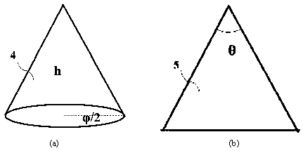
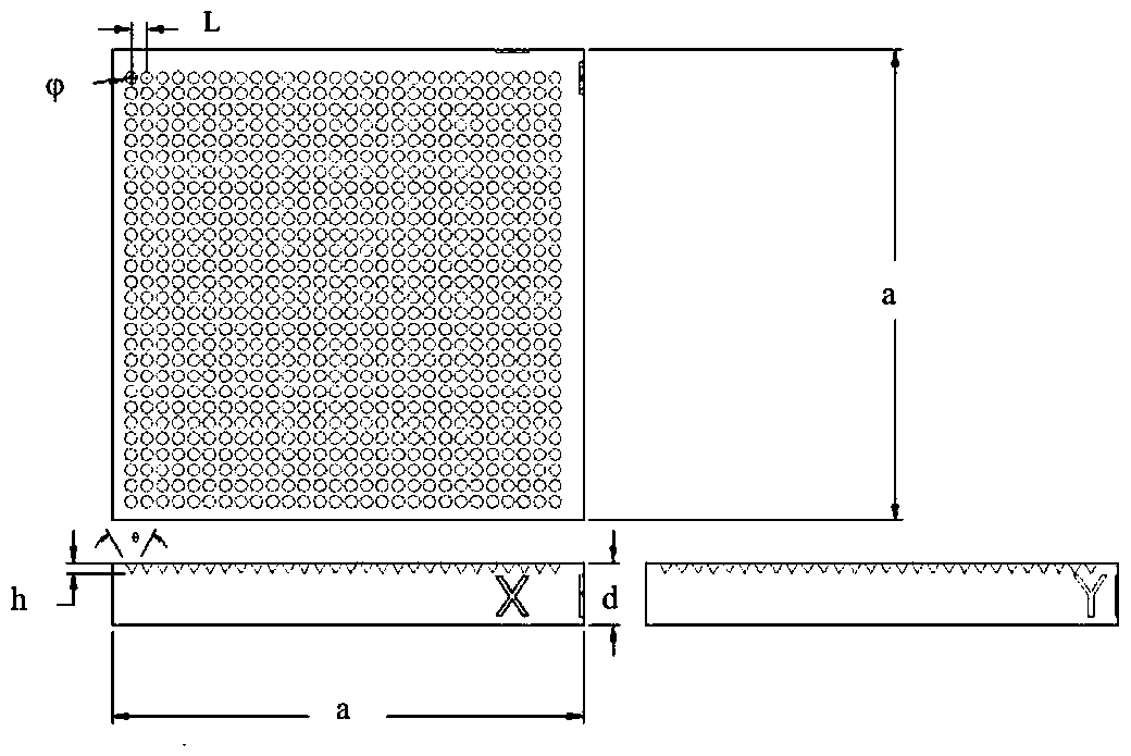
[0040] For the fluorescent ceramics with a surface light trap structure according to the present invention, 80g of YAG:0.1mol.% Ce ceramic powder is accurately weighed, 40g of photosensitive resin is added, and after blending, a planetary mill is used to fully mix to obtain a ceramic slurry. Such as figure 1 As shown, the designed ceramic surface structure parameters are: is 100 μm, h is 87 μm, and L is 150 μm, input into the 3D printer program. Pour the ceramic slurry into the trough of the 3D printer, and print the model of the fluorescent ceramic with the surface light trap structure and the model of the fluorescent ceramic without the surface light trap structure respectively, and finally obtain the ceramic green body with an ordered array structure on the surface and Fluorescent ceramic green body without surface light trap structure. Among them, the parameters of 3D printing include: the thickness of a single layer is 0.01mm; the number of printing layers is 40; the w...
Embodiment 2
[0042] Fluorescent ceramics with a surface light trap structure according to the present invention, accurately weigh 80g Al 2 o 3 / YAG: 0.4mol.% Ce ceramic powder, add 64g of photosensitive resin, after blending, use a planetary mill to fully mix to obtain ceramic slurry. Such as figure 1 As shown, the designed ceramic surface structure parameters are: is 10 μm, h is 10 μm, and L is 20 μm, input into the 3D printer program. Pour the ceramic slurry into the trough of the 3D printer, and print the model of the fluorescent ceramic with the surface light trap structure and the model of the fluorescent ceramic without the surface light trap structure respectively, and finally obtain the ceramic green body with an ordered array structure on the surface and Fluorescent ceramic green body without surface light trap structure. Among them, the parameters of 3D printing include: the thickness of a single layer is 0.04mm; the number of printing layers is 10; the wavelength of ultravi...
PUM
| Property | Measurement | Unit |
|---|---|---|
| thickness | aaaaa | aaaaa |
| thickness | aaaaa | aaaaa |
Abstract
Description
Claims
Application Information
 - R&D
- Intellectual Property
- Life Sciences
- Materials
- Tech Scout
- Unparalleled Data Quality
- Higher Quality Content
- 60% Fewer Hallucinations
Browse by: Latest US Patents, China's latest patents, Technical Efficacy Thesaurus, Application Domain, Technology Topic, Popular Technical Reports.
© 2025 PatSnap. All rights reserved.Legal|Privacy policy|Modern Slavery Act Transparency Statement|Sitemap|About US| Contact US: help@patsnap.com


