Environment-friendly microalgae cultivating method

A microalgae culture and environment-friendly technology, applied in the direction of microorganism-based methods, chemical instruments and methods, biochemical equipment and methods, etc., to achieve the effect of improving CO2 utilization and reducing costs

Inactive Publication Date: 2018-09-18
JIANGNAN UNIV
View PDF7 Cites 5 Cited by
  • Summary
  • Abstract
  • Description
  • Claims
  • Application Information

AI Technical Summary

Problems solved by technology

[0004] The cultivation of microalgae in wastewater can reduce the cost of microalgae cultivation, b

Method used


Image

  • Environment-friendly microalgae cultivating method
  • Environment-friendly microalgae cultivating method
  • Environment-friendly microalgae cultivating method

Examples


Embodiment 1

[0030] Example 1: Sludge dewatering solution

[0031] Municipal sewage was taken from the sludge dewatering liquid of a municipal sewage treatment plant in Wuxi City, Jiangsu Province (produced from the sludge dewatering process). After natural sedimentation, the water samples were filtered with filter paper (qualitative filter paper 11 cm) to remove larger particles in the sewage. Chlorella will be cultured in the sedimented and filtered sewage water samples, and the water quality indicators of the sludge dewatering solution are shown in Table 2.

[0032] Table 2 Water quality characteristics of sludge dewatering solution

[0033]

Embodiment 2

[0034] Example 2: Sludge dewatering solution coupled with CO 2 Photobioreactor for growing microalgae

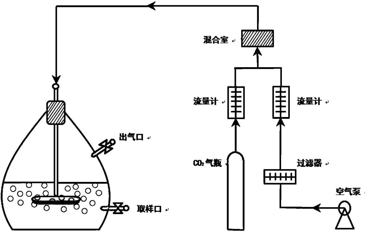
[0035] like figure 1 As shown, this experiment uses a 3.5L photobioreactor (PBR) as the experimental device, the sewage culture volume is 2.5L, and the reactor is provided with a sampling port and an air inlet and outlet. The reactor was placed in a constant temperature light incubator, the culture conditions were 25 ± 1 °C, and the light intensity was 50 μmol m -2 s -1 , the light-dark ratio is 12 / 12h (day / night). Set up different CO 2 Concentrations (5%, 10%, 15%, and 20%) Experimental group, and air was used as the control group. Aeration was performed at the beginning of the photoperiod, with sterile air and different concentrations of CO, respectively 2 gas. The flow rate was 250 mL / min and the time was 30 min.

Embodiment 3

[0036] Example 3: Different CO in sludge dewatering solution 2 Growth of Chlorella at Concentrations

[0037] The algae liquid grown to the exponential stage was centrifuged at 3000r / min for 5 minutes, washed three times with deionized water, and resuspended. In order to ensure the same initial conditions of the experiment, the inoculation density of algae in each experimental group was about 0.3g / L. pH. Regular sampling to determine the density of algae in water samples (OD) 680 ).

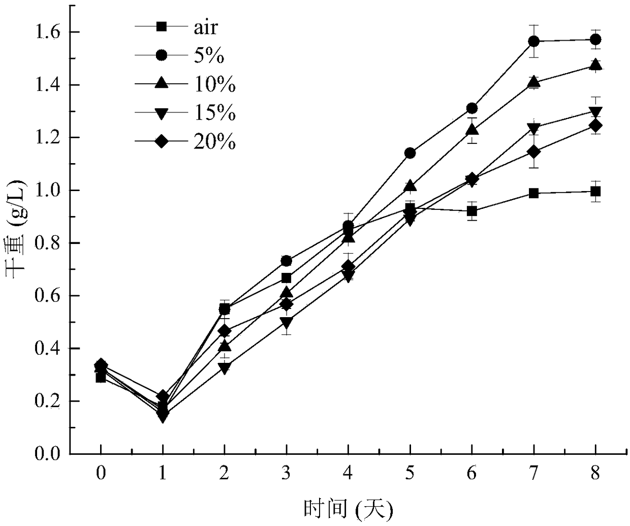
[0038] like figure 2 shown, for Chlorella at different CO 2 The change curve of biomass under concentration. Results After 8 days of culture, CO 2 The biomass obtained in the group was higher than that in the control group. It indicated that the organic carbon in the sludge dewatering solution could not meet the requirement of carbon source during the rapid growth of Chlorella, and Chlorella was in a carbon-limited culture condition. The aeration function fully mixes the algae liquid to ...


PUM


Abstract

The invention discloses an environment-friendly microalgae cultivating method, and belongs to the field of environmental engineering and microalgae biotechnologies. The method is capable of using CO2in different concentrations as a carbon source of chlorella growth, adding the CO2 to sludge dehydrated liquid, and improving a biomass of chlorella. The method has the advantages of using a flue gasCO2 as the carbon source which is added into the sludge dehydrated liquid for cultivating the chlorella, generating a biomass energy and recycling nitrogen and phosphorus in sewage at the same time, and reducing the cost of sewage treatment. The environmental benefit and the economic benefit are realized simultaneously. In addition, the chlorella absorbs and uses the CO2, the setting treatment cost of the CO2 is reduced, and other nitrogen-phosphorus and carbon sources cannot be added in a cultivation process so as to obtain the considerable biomass.

Description

technical field [0001] The invention relates to an environment-friendly microalgae cultivation method, which belongs to the field of environmental engineering and microalgae biotechnology. Background technique [0002] Microalgae have high photosynthetic efficiency, short growth cycle, and can tolerate high concentrations of CO 2 , Strong environmental adaptability, can use light energy to convert inorganic carbon source CO 2 It is synthesized into its own substances and metabolites to obtain high value-added products (biodiesel, protein, etc.), and at the same time, it can improve air quality and alleviate the global greenhouse effect. Microalgae carbon sequestration technology is a green, environmentally friendly, efficient and economical CO 2 Emission reduction technology is of great significance in environmental protection, energy production, and circular economy. [0003] Due to the acceleration of urbanization in my country, the amount of municipal sewage treatment ...

Claims


Application Information

Patent Timeline
IPC IPC(8): C12N1/12C12N1/20C02F3/32C02F3/34C12R1/89
CPCC02F3/322C02F3/34C12N1/12C12N1/20
Inventor 任洪艳脱金华阮文权
Owner JIANGNAN UNIV
Why Eureka
Try Eureka