3D printing method of diamond drill bit with grinding aid structure

A diamond drill bit, 3D printing technology, applied in the direction of drill bit, earthwork drilling, drilling equipment, etc., can solve the problems of low efficiency, weak abrasiveness, difficult to drill into rock formations, etc., achieve excellent performance, increase drilling speed, consume drilling pressure little effect

Active Publication Date: 2020-05-22
CHINA UNIV OF GEOSCIENCES (WUHAN)
View PDF8 Cites 0 Cited by
  • Summary
  • Abstract
  • Description
  • Claims
  • Application Information

AI Technical Summary

Problems solved by technology

[0005] At present, the existing diamond drill bits are difficult to drill into hard, dense and weakly abrasive rock formations in prospecting engineering, and even if they drill, the efficiency is extremely low

Method used


Image

  • 3D printing method of diamond drill bit with grinding aid structure
  • 3D printing method of diamond drill bit with grinding aid structure
  • 3D printing method of diamond drill bit with grinding aid structure

Examples


Embodiment 1

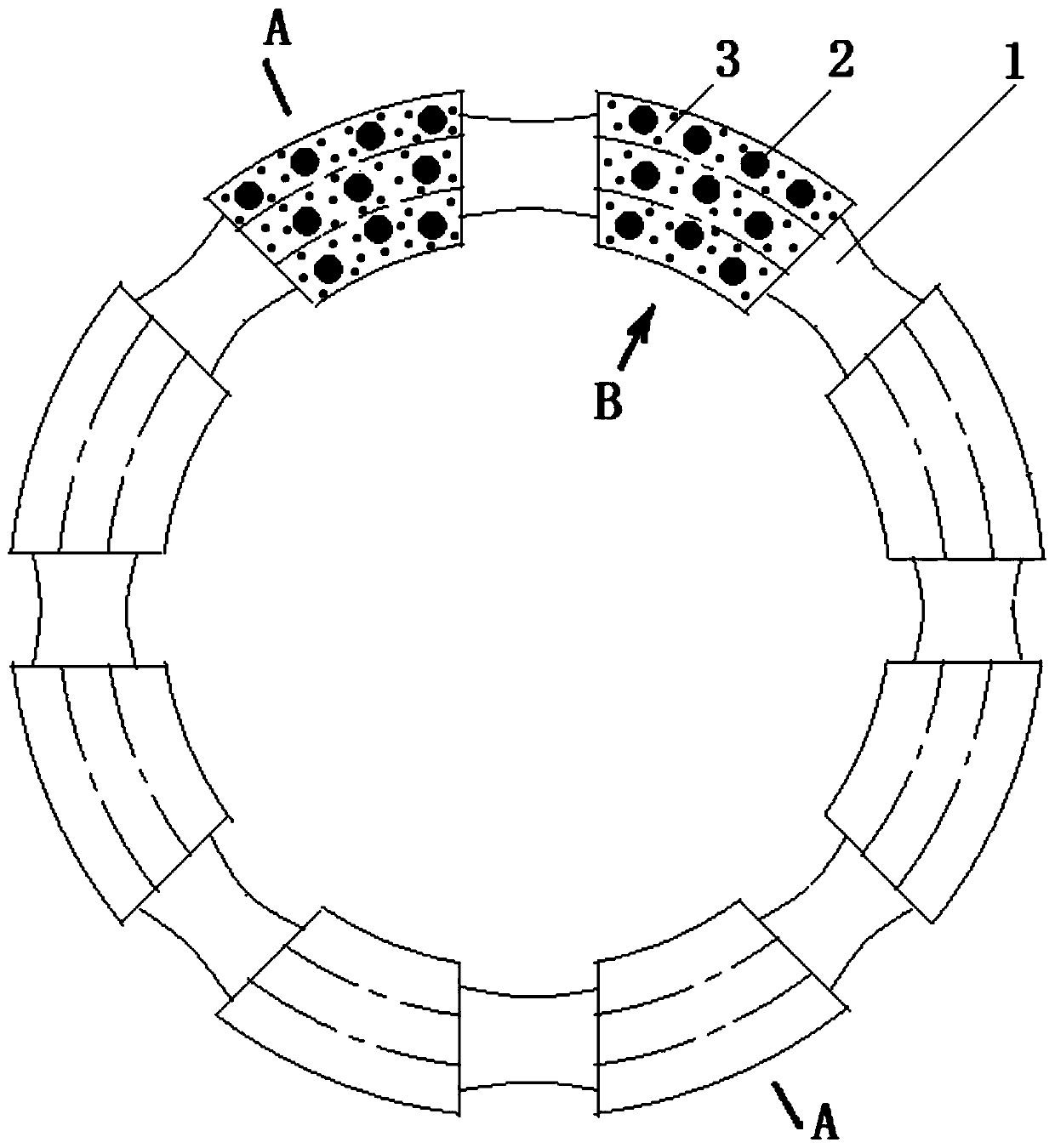
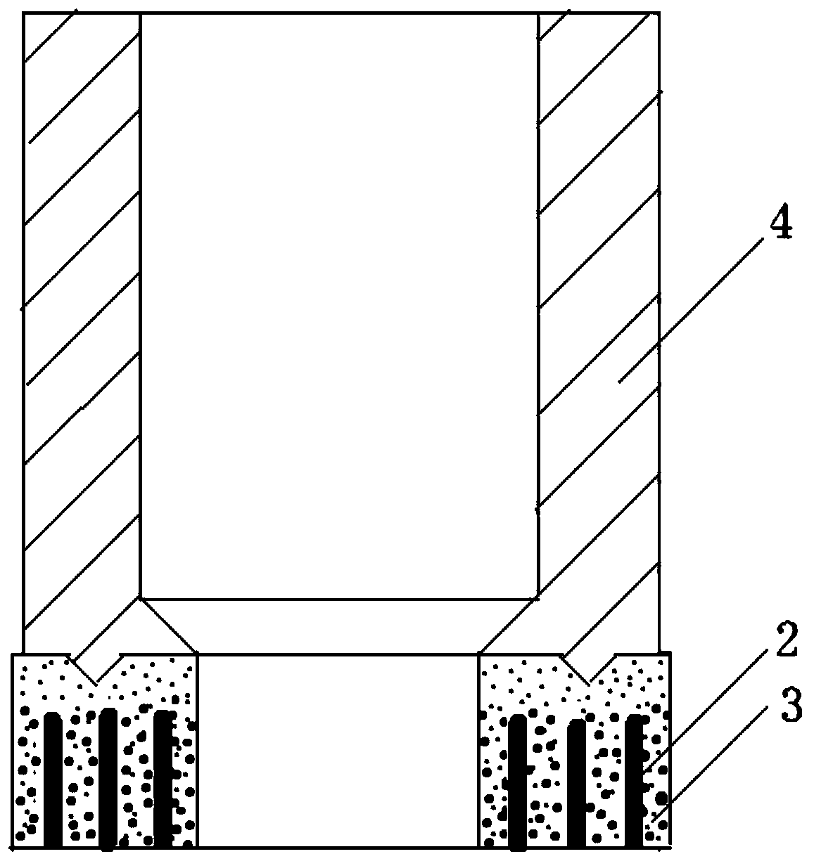
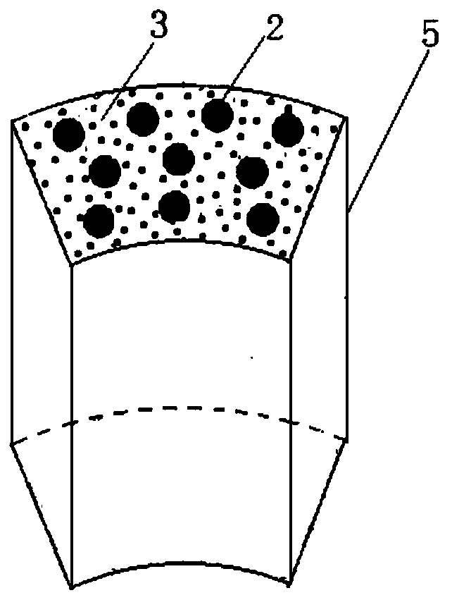
[0034] Please refer to Figure 1-3 , the embodiment of the present invention provides a diamond drill bit with a grinding aid structure, the drill bit includes a plurality of main working bodies 3 and a plurality of grinding aids 2 placed in the main working body, the grinding aids 2 and the main working body The working body 3 constitutes a drill fan-shaped working body 5 .

[0035] A plurality of main working bodies 3 are arranged at equal intervals along the circumferential direction of the bottom lip surface of the drill bit, and are located on the edge of the bottom lip surface. The Rockwell hardness of the main working bodies 3 is HRC12-25, and the wear resistance is ML (0.5-0.7)× 10 -5 , the main working body 3 is connected to the adjacent main working body through the nozzle 1.

[0036] A plurality of grinding aids 2 are arranged in the main working body 3 and are evenly distributed. Preferably, the grinding aids 2 are arranged on the radius of the bottom lip surface...

Embodiment 2

[0051] The difference between this embodiment and Example 1 is that the FAM-103 type pre-alloyed powder accounts for 68% of the main working body raw materials, the FAM-201 type pre-alloyed powder accounts for 32%, and the particle size of the diamond is 35 mesh to 40 mesh. The particle size of the alloy powder is 127μm, and the volume concentration of diamond is 22%. Among the grinding aid raw materials, FAM-201 type pre-alloyed powder accounts for 70%, FAM-202 type pre-alloyed powder accounts for 30%, and the particle size of silicon carbide is 45 mesh. ~50 mesh, the volume concentration of silicon carbide is 8%; the parameters of the forming drill bit of the laser selective melting equipment are: laser power 220W, scanning speed 700mm / s, scanning distance 0.06mm, powder coating thickness 0.5mm. The rest are basically the same as in Example 1.

Embodiment 3

[0053] The difference between this embodiment and Example 1 is only that the FAM-103 type pre-alloyed powder accounts for 72% of the main working body raw materials, the FAM-201 type pre-alloyed powder accounts for 28%, and the particle size of the diamond is 50 mesh to 60 mesh. The volume concentration of the pre-alloyed powder is 20%, and the particle size of the pre-alloyed powder is 80 μm; the FAM-201 type pre-alloyed powder accounts for 65%, the FAM-202 type pre-alloyed powder accounts for 35%, and the particle size of the silicon carbide is 50 mesh to 60 The volume concentration of silicon carbide is 10%, the particle size of the pre-alloyed powder is 127μm; the parameters of the forming drill bit of the laser selective melting equipment are: laser power 200W, scanning speed 800mm / s, scanning distance 0.07mm, powder coating thickness 0.40 mm. The rest are basically the same as in Example 1.

[0054] The main working body of the diamond drill bit of the present invention...


PUM

PropertyMeasurementUnit
particle sizeaaaaaaaaaa
particle diameteraaaaaaaaaa
particle sizeaaaaaaaaaa

Abstract

The invention discloses a diamond drill bit with a grinding aid structure. The drill bit comprises a plurality of main working bodies arranged along the circumferential direction of the bottom lip surface of the drill bit and a plurality of grinding aid bodies arranged in the main working body. The working body and the adjacent main working body are connected by nozzles, the grinding aids are evenly distributed in the main working body at equal intervals, and the total area of ​​the cross section of the grinding aids is 30% to 38% of the total area of ​​the main working body. %, the grinding-aid body is a cylinder with a diameter of 3-5 mm and a height of 12-15 mm, the main working body plays the role of main body breaking rocks, and the grinding-aid body plays the role of auxiliary and indirect rock breaking. Also disclosed is a 3D printing technology method for a diamond drill bit with a grinding aid structure. The diamond drill bit of the invention can effectively overcome the difficult problem of drilling into hard and dense rock formations.

Description

technical field [0001] The invention relates to the field of new materials and manufacturing technology, in particular to a diamond drill bit with a grinding aid structure and a 3D printing method thereof. Background technique [0002] Diamond drill bits have been developed for decades and are widely used in geological exploration, oil drilling, mining and geological disaster prevention and other industries. [0003] Diamond drill bits have been manufactured using hot pressing methods, pressureless impregnation methods, cold pressing sintering methods, hot isostatic pressing methods, and electroplating methods. However, the carcass alloy of the diamond drill bit produced by these conventional methods is not a real alloy, and the diamond bezel setting is mainly mechanically set, and the firmness of the bezel setting is low, which affects the quality of the drill bit. Secondly, conventional methods have many limitations in the manufacture of diamond drill bits with complex st...

Claims


Application Information

Patent Timeline
Patent Type & Authority Patents(China)
IPC IPC(8): E21B10/46B22F3/105B22F3/24C22C26/00B33Y10/00B33Y70/00B33Y80/00
CPCE21B10/46C22C26/00B22F3/24B33Y10/00B33Y70/00B33Y80/00B22F2003/248B22F10/00B22F10/36B22F10/64B22F10/28B22F10/366B22F10/32Y02P10/25
Inventor 杨展段隆臣杨洋谭松成
Owner CHINA UNIV OF GEOSCIENCES (WUHAN)
Why Eureka
Try Eureka