
A boosted single-phase seven-level inverter

A seven-level inverter technology, applied in the direction of adjusting electrical variables, instruments, electrical components, etc., can solve the problems of increasing system cost and complex topology structure, and achieve the effect of low hardware cost and small number of switches

Inactive Publication Date: 2020-06-26
XIAN UNIV OF TECH
View PDF5 Cites 0 Cited by
  • Summary
  • Abstract
  • Description
  • Claims
  • Application Information

AI Technical Summary

Problems solved by technology

At present, the main structures of multi-level inverters are diode clamp type and flying capacitor type. With the increase of the number of levels, the topology structure will become too complicated, which will increase the system cost, and it is generally only suitable for high-power applications.

Method used


Image

  • A boosted single-phase seven-level inverter
  • A boosted single-phase seven-level inverter
  • A boosted single-phase seven-level inverter

Examples


Embodiment Construction

[0022] The present invention will be further described in detail below in conjunction with the accompanying drawings and specific embodiments, but the present invention is not limited to these embodiments.

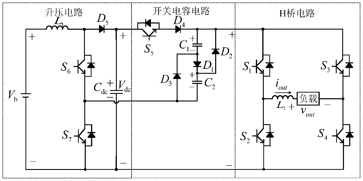
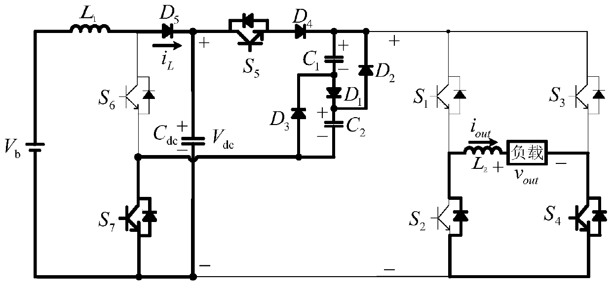
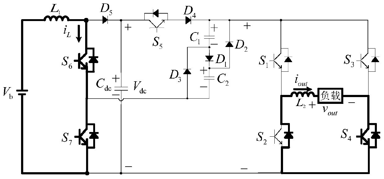
[0023] The present invention provides a step-up single-phase seven-level inverter, such as figure 1 As shown, the inverter includes a boost circuit, a switched capacitor circuit and an H-bridge circuit. The specific description is as follows:

[0024] The boost circuit includes: DC power supply V b , switch tube S 6 , S 7 , Diode D 5 and capacitance C dc , DC supply V b The positive connection of the inductance L 1 One end of the DC power supply V b The negative pole of the switch tube S 7 output and the capacitor C dc of the negative connection, the inductor L 1 The other end is connected with the diode D 5 The anode and the power switch tube S 6 The inputs are connected together, the diode D 5 The cathode and capacitance C dc the positive connection of the ...


PUM


Abstract

The invention discloses a boost single-phase seven-level inverter. The boost single-phase seven-level inverter comprises a boost circuit, a switch capacitance circuit and an H-bridge circuit. A switchtube in the boost circuit is used for controlling a capacitance voltage, so that the output voltage amplitude is increased, an input range of the voltage becomes wide, and the boost single-phase seven-level inverter is applicable to an occasion with relatively high input voltage; by joint matching of the boost circuit and the H-bridge inversion circuit, the inverter outputs different level modesand is endowed with automatic voltage sharing capability, and the control algorithm is simplified; meanwhile, the seven-level inverter can works in an active inversion mode and also can work in a passive inversion mode; and moreover, a few switches are involved, and the hardware cost is low.

Description

technical field [0001] The invention belongs to the technical field of power electronics and relates to a step-up single-phase seven-level inverter. Background technique [0002] With the rapid development of new energy sources such as solar energy, wind energy, biomass energy, tidal energy and geothermal energy, sufficient new energy can effectively alleviate the energy crisis and reduce environmental pollution. At present, distributed grid-connected power generation technology is mainly used to realize the utilization of new energy. The key technology of grid-connected power generation is to adopt a reasonable inverter topology and grid-connected control strategy in order to obtain a stable grid-connected system and high-quality grid-connected current. [0003] Compared with the traditional two-level inverter, the multi-level inverter has the advantages of smaller output current harmonics, higher voltage level and small size filter, so it has been widely used in the field...

Claims


Application Information

Patent Timeline
Patent Type & Authority Patents(China)
IPC IPC(8): H02M7/483H02M7/5387H02M3/158
CPCH02M3/158H02M7/483H02M7/5387Y02B70/10
Inventor 张琦李江江孙向东任碧莹安少亮许江涛文阳阳
Owner XIAN UNIV OF TECH
Learn More