Laser-induced photothermal expansion drive device

A driving device and thermal expansion technology, which is applied in the drive of manipulators, medical equipment and industrial mechanical devices, and in the field of robots, can solve the problems of inability to realize control, difficulty in miniaturization and integration, high energy consumption, etc., and achieve excellent photothermal and electric co-expansion drive function , easy integration and miniaturization, and the effect of improving work performance

Inactive Publication Date: 2019-12-17
CHINA UNIV OF GEOSCIENCES (WUHAN)
View PDF6 Cites 0 Cited by
  • Summary
  • Abstract
  • Description
  • Claims
  • Application Information

AI Technical Summary

Problems solved by technology

Electrostatic driving is driven by the electrostatic charge Coulomb force between electrostatic fields. Piezoelectric driving uses the inverse piezoelectric effect of piezoelectric crystals to generate changes in elongation through an externally applied electric field, which requires a higher driving voltage and exists an electromagnetic force. Interference is difficult to eliminate, and it is not easy to miniaturize and integrate
Electromagnetic drive uses electricity in the excitation coil to generate an electromagnetic field to move the magnetic conductor in the magnetic field, which has disadvantages such as large volume, high energy consumption, large temperature drift noise, and difficulty in miniaturization and integration.
Although the size of the main body of some driving mechanisms can be made smaller, they all need to be connected to an external low-voltage or high-voltage control source through wires. There is a problem that it is not easy to miniaturize the overall structure, and the wire connection also restricts the application range, and it is not easy to connect the driving mechanism. It is integrated in the microsystem as a whole, so it cannot realize the control in special environments such as long-distance or small pipelines

Method used


Image

  • Laser-induced photothermal expansion drive device
  • Laser-induced photothermal expansion drive device
  • Laser-induced photothermal expansion drive device

Examples


Embodiment 1

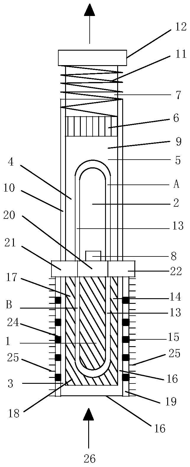
[0024] Embodiment 1 of the present invention provides a laser-induced photothermal expansion driver (see figure 1 ), including: including: laser heating and cooling two-way worker 1, photothermal expansion conversion driver 2; laser heating and cooling two-way worker 1, including: laser, graphene-type laser thermoelectric converter 3; photothermal expansion conversion driver 2 , including: photothermal phase change expansion driver 4; photothermal phase change expansion driver 4, including: photothermal phase change expansion material 5, liquid metal 13, liquid metal U-shaped tube A, photothermal expansion drive piston 6, light Thermal expansion drive rod 7, temperature sensor 8, cylinder body 9, heat insulation layer 10, ordinary spring 11, optical thermal expansion driving force output end 12; liquid metal 13 is assembled in liquid metal U-shaped tube A; liquid metal U-shaped tube A, optical The thermal phase change expansion material 5, the photothermal expansion driving pi...

Embodiment 2

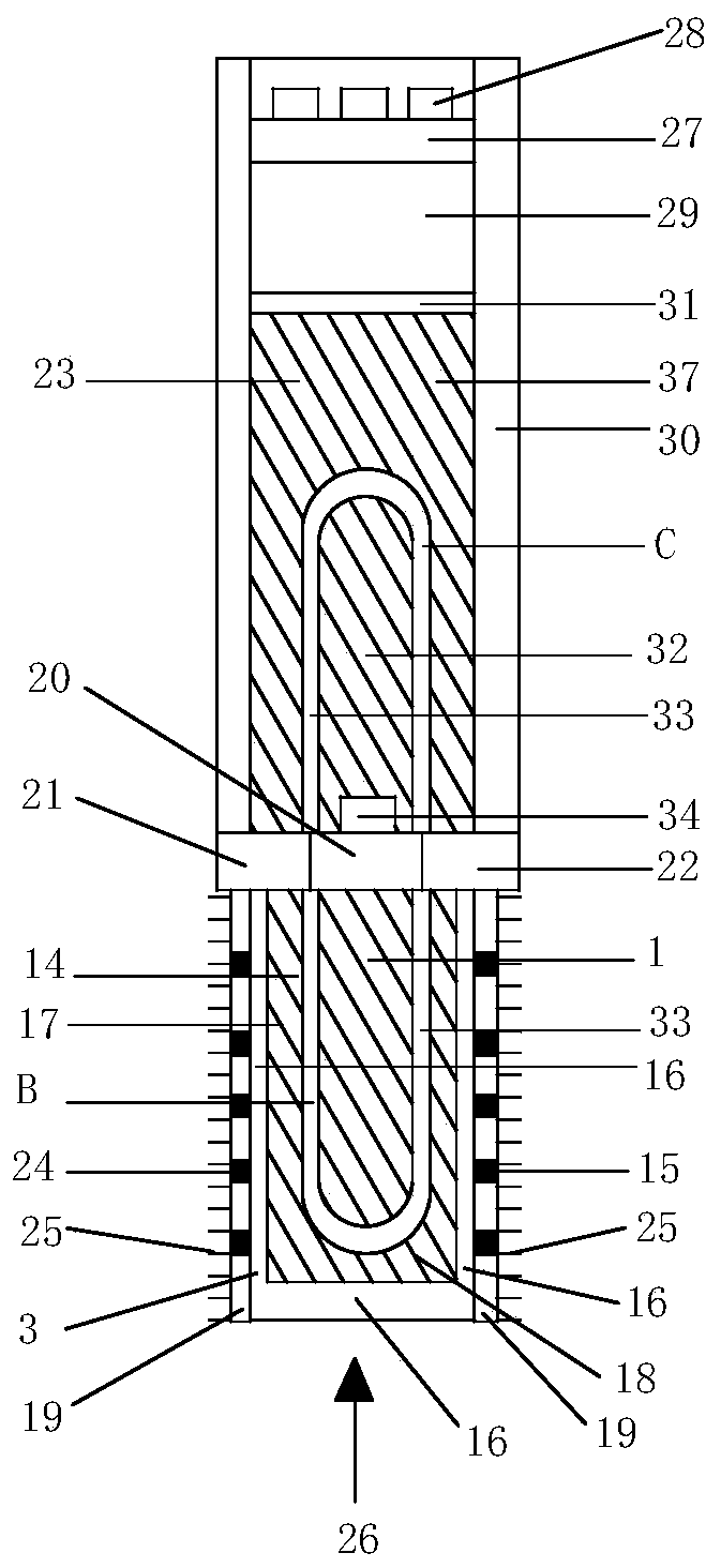
[0033] Embodiment 2 of the present invention provides a laser-induced photothermal expansion-driven microvalve (see figure 2 ), including: laser heating and cooling two-way worker 1, photothermal expansion-driven microvalve 23; said photothermal expansion-driven microvalve 23, including: graphene type liquid metal heater 37, polymer driving layer 27, micro Channel matrix 28, cavity 29, heat insulating layer 30; graphene-type liquid metal heater 37, including: second graphene layer 31, graphene heat conduction composite matrix 32, high-temperature liquid metal 33, liquid metal U-shaped tube C, Temperature sensor 34; high-temperature liquid metal 33 is assembled in liquid metal U-shaped tube C; liquid metal U-shaped tube C and temperature sensor 34 are assembled in graphene thermally conductive composite matrix 32; graphene thermally conductive composite matrix 32 passes through the second graphite The alkene layer 31 is closely connected with the cavity 29; the other end of th...

Embodiment 3

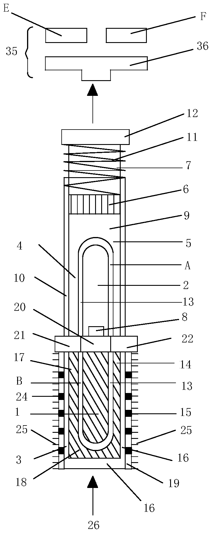
[0040] Embodiment three of the present invention provides a laser-induced photothermal expansion driven relay (see image 3 ), including: laser-induced thermal expansion drivers (see figure 1 , image 3 ), photothermal expansion driven relay 35 (see image 3 ); the photothermal expansion driven relay 35 includes: photothermal expansion driven linear moving piece 36, contact E, contact F; photothermal expansion driven linear moving piece 36 is close to the photothermal expansion driving force output end 12 of the laser-induced photothermal expansion driver. The laser-induced photothermal expansion driver (the working principle and process are the same as those in Embodiment 1) and the photothermal expansion-driven relay jointly constitute the laser-induced photothermal expansion-driven relay. Driven by the photothermal expansion driving force output end 12 of the laser-induced photothermal expansion driver, the photothermal expansion driven linear moving piece 36 can move lin...


PUM


Abstract

The invention discloses a laser-induced photo-thermal expansion type driving device. The laser-induced photo-thermal expansion type driving device comprises a laser-induced thermal and refrigeration bidirectional working device and a photo-thermal expansion conversion driver. The laser-induced thermal and refrigeration bidirectional working device is tightly connected with the photo-thermal expansion conversion driver. The laser-induced thermal and refrigeration bidirectional working device is connected with a photo-thermal expansion driving type micro valve of a laser-induced photo-thermal expansion driving type micro valve. The photo-thermal expansion conversion driver comprises a photo-thermal-induced material phase change expansion driver or a photo-thermal-induced material thermal expansion driver. The photo-thermal-induced material phase change expansion driver or the photo-thermal-induced material thermal expansion driver includes a photo-thermal expansion driving force output end. The photo-thermal expansion driving force output end pushes a photo-thermal expansion driving linear moving piece of a laser-induced photo-thermal expansion driving type relay to move and to be incontact with a contact to form a conduction loop. The laser-induced photo-thermal expansion type driving device can be used in the field of driving robots, manipulators, medical instruments and industrial mechanical devices.

Description

technical field [0001] The present invention relates to the driving field of robots, manipulators, medical equipment and industrial mechanical devices, and to the photothermal driving application technology of laser or solar energy concentration, and more specifically, to a laser-induced photothermal expansion type driving device. Background technique [0002] In the application fields of robots, manipulators, medical equipment and industrial machinery, drive components and drive technology are the core and important parts, requiring drive components to have the advantages of high efficiency and easy control. At present, the micro-drive mechanisms that are mature and widely used mainly include electrostatic drive type, photostrictive type, electromagnetic drive type, thermal expansion type, piezoelectric drive type, ultrasonic type, memory alloy type, magnetostrictive type, etc. Electrostatic driving is driven by the electrostatic charge Coulomb force between electrostatic f...

Claims


Application Information

Patent Timeline
Patent Type & Authority Patents(China)
IPC IPC(8): F03G7/06H02N11/00
CPCF03G7/06H02N11/002
Inventor 袁曦明袁一楠
Owner CHINA UNIV OF GEOSCIENCES (WUHAN)
Why Eureka
Try Eureka