Method for continuously reducing temperature rise in using process of accumulator

A technology of temperature rise and storage battery, which is applied in the direction of secondary batteries, battery pack components, circuits, etc., can solve the problems of inability to conduct heat in time and the active material of the battery falls off, and achieve reasonable cost, low input cost and extended service life Effect

Active Publication Date: 2018-10-19
ZHEJIANG UNIVERSITY OF SCIENCE AND TECHNOLOGY
View PDF4 Cites 0 Cited by
  • Summary
  • Abstract
  • Description
  • Claims
  • Application Information

AI Technical Summary

Problems solved by technology

[0009] The present invention aims at the above-mentioned problems existing in the use of the storage battery, and provides a method for continuously reducing the temperature rise of the storage battery during use. The present invention continuously cools the storage battery in use to solve the problem that the heat generated by the storage battery during use cannot be conducted in time As a result, the internal temperature of the battery is high and the active material falls off, etc.

Method used


Image

  • Method for continuously reducing temperature rise in using process of accumulator

Examples

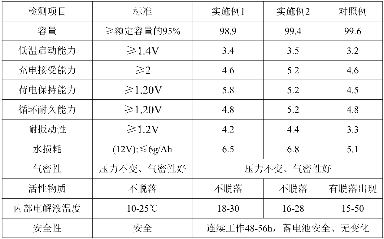

Embodiment 1

[0031] The invention provides a method for continuously reducing the temperature of battery electrode plates, which is realized by the following method: add a layer of protective layer shell to the battery shell, and leave a gap of 0.3-1cm between the protective layer shell and the battery shell. filled with liquid nitrogen.

[0032] Wherein the protective layer shell includes the following components by mass: 15 parts of stearic acid, 16 parts of aromatic essential oil, 12 parts of charcoal ash, 7 parts of calcium peroxide, 40 parts of terpene resin modified volcanic ash, and 3 parts of microcrystalline cellulose , 2.5 parts of crospovidone, 2 parts of sepiolite fiber, 1 part of polyvinyl alcohol resin, 4 parts of salicylic acid, 1.5 parts of hydrogenated rosin pentaerythritol ester, 1 part of polytetrafluoroethylene superfine powder, 2 parts of polylactic acid , 0.8 parts of diphenylmethane bismaleimide, 0.5 parts of sulfated castor oil, 0.3 parts of allyl glycidyl ether, 0....

Embodiment 2

[0049] The invention provides a method for continuously reducing the temperature of battery electrode plates, which is realized by the following method: add a layer of protective layer shell to the battery shell, and leave a gap of 0.3-1cm between the protective layer shell and the battery shell. filled with liquid nitrogen.

[0050] Wherein the protective layer shell includes the following components by mass: 6 parts of stearic acid, 15 parts of aromatic essential oil, 10 parts of charcoal ash, 7 parts of calcium peroxide, 40 parts of terpene resin modified volcanic ash, and 2 parts of microcrystalline cellulose , 3 parts of crospovidone, 2 parts of sepiolite fiber, 1.5 parts of polyvinyl alcohol resin, 6 parts of salicylic acid, 1 part of hydrogenated rosin pentaerythritol ester, 0.5 part of polytetrafluoroethylene superfine powder, 5 parts of polylactic acid , 1 part of diphenylmethane bismaleimide, 0.8 part of sulfated castor oil, 0.4 part of allyl glycidyl ether, 0.5 part...


PUM

PropertyMeasurementUnit
Thicknessaaaaaaaaaa
Thicknessaaaaaaaaaa
Thicknessaaaaaaaaaa

Abstract

The invention discloses a method for continuously reducing temperature rise in a using process of an accumulator, and relates to the related technical field of battery active substance falling. The method comprises the following steps: additionally installing a layer of a protecting layer housing on the periphery of an accumulator housing, and reserving 0.3-1 cm of a gap between the protecting layer housing and the accumulator housing, wherein the gap is filled with liquid nitrogen. The method is capable of, through continuously reducing a temperature of the accumulator in use, solving a problem that generated heat of the accumulator in use cannot be conducted in time so that phenomena, such as active substance falling, are caused by a high internal temperature of the accumulator, the method is simple, convenient, and low in investment cost, and capable of, through combining a prepared heat-transfer material, reducing the temperature of the accumulator, and prolonging the service lifeof the active substance and the accumulator.

Description

Technical field: [0001] The invention relates to the technical field related to the shedding of battery active substances, in particular to a method for continuously reducing the temperature rise of a storage battery during use. Background technique: [0002] Lead-acid batteries, lead-acid batteries have stable working voltage, wide range of operating temperature and operating current, can charge and discharge hundreds of cycles, good storage performance (especially suitable for dry charging storage), and low cost, so they are widely used. Its size and weight have not been effectively improved, so it is most commonly used in automobiles and motorcycles. The biggest improvement of the lead-acid battery is the recent use of high-efficiency oxygen recombination technology to complete water regeneration, so as to achieve the purpose of being completely sealed without adding water, and the resulting "water-free battery" has a lifespan of up to 4 years. [0003] The composition o...

Claims


Application Information

Patent Timeline
IPC IPC(8): H01M2/02H01M10/613H01M50/124
CPCH01M10/613H01M50/124Y02E60/10
Inventor 丘焕山
Owner ZHEJIANG UNIVERSITY OF SCIENCE AND TECHNOLOGY
Why Eureka
Try Eureka