Quantum dot light emitting diode and preparation method thereof
A quantum dot light-emitting and diode technology, applied in electrical components, circuits, semiconductor devices, etc., can solve the problem of unbalanced carrier injection, affecting the performance of QLED devices, etc., to enhance the hole injection ability, easy to realize industrialization, Mature and controllable effects
- Summary
- Abstract
- Description
- Claims
- Application Information
AI Technical Summary
Problems solved by technology
Method used
Image

Examples
preparation example Construction
[0029] And, the embodiment of the present invention also provides a method for preparing a quantum dot light-emitting diode, comprising the following steps:
[0030] S01. Configure a hole injection material solution containing 2D TMDs / C composite material, and provide a patterned anode substrate;
[0031] S02. Depositing the hole injection material solution on the patterned anode substrate to prepare a hole injection layer;
[0032] S03. Depositing a hole transport layer, a quantum dot light-emitting layer, an electron transport layer and a cathode sequentially on the hole injection layer.
[0033] Specifically, in the above step S01, preferably, the preparation method of the 2D TMDs / C composite material is:
[0034] S011. Provide organic carbon source;
[0035] The organic carbon source can be purchased or obtained by self-preparation. Specifically, the organic carbon source includes but not limited to polyaniline.
[0036] As a specific example, the preparation method of t...
Embodiment 1
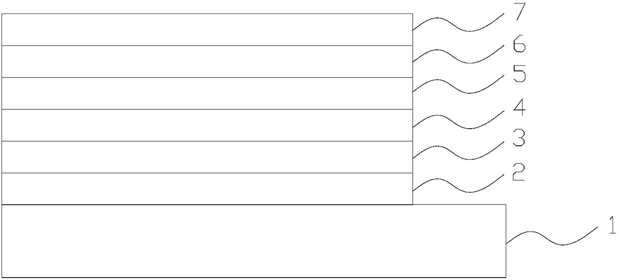
[0052] A quantum dot light-emitting diode, comprising a substrate, an anode, a hole injection layer, a hole transport layer, a quantum dot light-emitting layer, an electron transport layer, and a cathode that are sequentially stacked, wherein the hole injection layer is made of MoS 2 / C composite material.
[0053] The preparation method of the quantum dot light-emitting diode comprises the following steps:
[0054] S11. configuring a hole injection material solution containing a 2D TMDs / C composite material, and providing a patterned anode substrate;
[0055] The patterned ITO substrate was placed in acetone, lotion, deionized water and isopropanol in order for ultrasonic cleaning, and each step of ultrasonic cleaning lasted for about 15 minutes. After the ultrasound is completed, place the ITO in a clean oven to dry for later use.
[0056] After the ITO substrate was dried, the ITO surface was treated with oxygen plasma for 5 minutes to further remove the organic matter at...
Embodiment 2
[0064] A quantum dot light-emitting diode, comprising a substrate, an anode, a hole injection layer, a hole transport layer, a quantum dot light-emitting layer, an electron transport layer, and a cathode that are sequentially stacked, wherein the hole injection layer is made of MoS 2 / C composite and PEDOT:PSS.
[0065] The preparation method of the quantum dot light-emitting diode comprises the following steps:
[0066] S21. configuring a hole injection material solution containing a 2D TMDs / C composite material, and providing a patterned anode substrate;
[0067] The patterned ITO substrate was placed in acetone, lotion, deionized water and isopropanol in order for ultrasonic cleaning, and each step of ultrasonic cleaning lasted for about 15 minutes. After the ultrasound is completed, place the ITO in a clean oven to dry for later use.
[0068] After the ITO substrate was dried, the ITO surface was treated with oxygen plasma for 5 minutes to further remove the organic matt...
PUM
 Abstract
Description
Claims
Application Information