A frequency tunable antenna and its manufacturing method

An antenna and frequency technology, applied in the field of frequency adjustable antenna and its production, can solve the problems of increasing cost, increasing process complexity, and failing to achieve electron mobility

Active Publication Date: 2021-04-23
BOE TECH GRP CO LTD +1
View PDF1 Cites 0 Cited by
  • Summary
  • Abstract
  • Description
  • Claims
  • Application Information

AI Technical Summary

Problems solved by technology

However, due to the need to make antennas on glass today, because traditional glass thin film transistors cannot achieve the extremely high electron mobility required by variable capacitors, it is necessary to use semiconductor diodes to make variable capacitors in glass substrates, but this In other cases, it is necessary to weld or punch the variable capacitance diode of single crystal silicon or gallium arsenide to the glass substrate, which needs to increase the existing TFT-LCD process flow for manufacturing glass substrate antennas, because it is not the process of making glass substrates. The standard process flow of the TFT-LCD factory will increase the complexity of the process, thereby increasing the cost

Method used


Image

  • A frequency tunable antenna and its manufacturing method
  • A frequency tunable antenna and its manufacturing method
  • A frequency tunable antenna and its manufacturing method

Examples


Embodiment 1

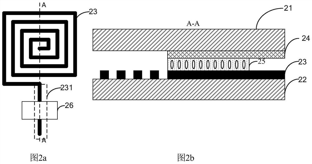
[0070] refer to Figure 2a with 2b as shown ( Figure 2a It is a top view of the frequency adjustable antenna, 2b is an enlarged cross-sectional view of the frequency adjustable antenna), this embodiment provides a frequency adjustable antenna as a coil antenna, including:

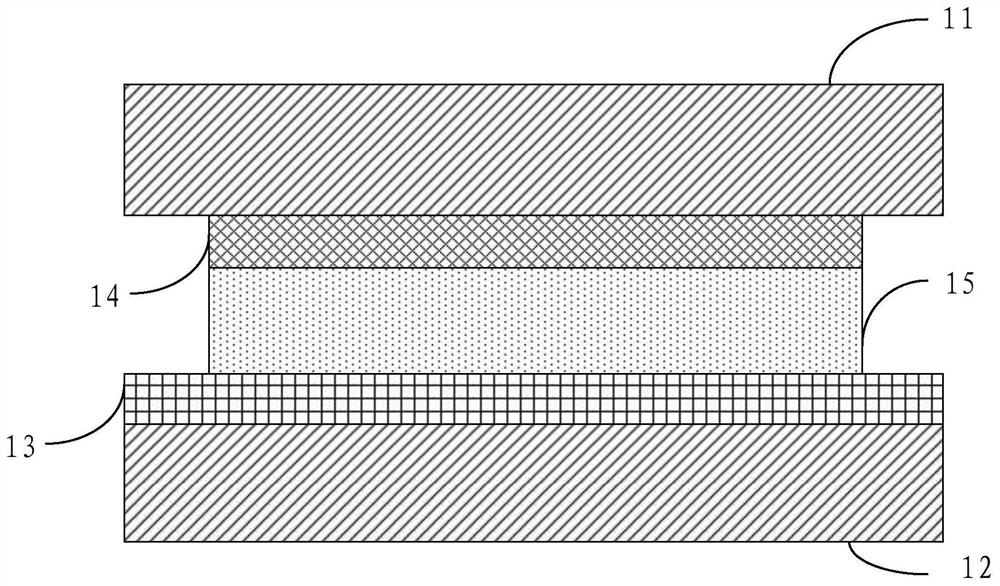
[0071] The first substrate 21 and the second substrate 22 facing each other, the coil electrode 23 disposed on the second substrate 22 on the side close to the first substrate 21, and the antenna disposed on the side of the first substrate 21 close to the second substrate 22 are grounded. Pole 24; Exemplarily, in the embodiment of the present invention, the liquid crystal drive electrode is an antenna ground electrode, and the antenna electrode is a coil electrode 23 wound in a preset direction, specifically a microstrip line;

[0072] Wherein, the liquid crystal layer 25 is arranged between the feeding part 231 of the coil electrode 23 and the antenna ground electrode 24; wherein, the orthographic proje...

Embodiment 2

[0078] refer to Figure 3a with 3b as shown ( Figure 3a It is a top view of the slot-coupled patch antenna, 3b is an enlarged cross-sectional view of the slot-coupled patch antenna), and this embodiment provides a frequency-tunable antenna as a slot-coupled patch antenna, including:

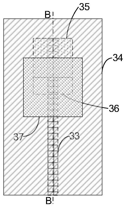
[0079] The first substrate 31 and the second substrate 32 facing each other, the antenna electrode 33 disposed on the second substrate 32 on the side close to the first substrate 31, and the antenna electrode 33 disposed on the side of the first substrate 31 close to the second substrate 32 are grounded. Pole 34; Exemplarily, in the embodiment of the present invention, the liquid crystal driving electrode is an antenna ground electrode, and the antenna electrode is a microstrip line;

[0080] The frequency adjustable antenna also includes a patch electrode 37, the patch electrode 37 is arranged on the side of the first substrate 31 away from the second substrate 32, the antenna ground electrod...

Embodiment 3

[0086] refer to Figure 4a with 4b as shown ( Figure 4a is a top view of the coplanar waveguide feeding coil antenna, 4b is an enlarged cross-sectional view of the coplanar waveguide feeding coil antenna), and this embodiment provides a frequency adjustable antenna which is a coplanar waveguide feeding coil antenna.

[0087] The coplanar waveguide feeding coil antenna includes a first substrate 41 and a second substrate 42 opposite to each other, a coplanar waveguide electrode 43 disposed on the second substrate 42 close to the first substrate 41, and a coplanar waveguide electrode 43 disposed on the first substrate 41 close to the first substrate 41. The liquid crystal driving electrode 44 on one side of the second substrate 42 ; for example, in the embodiment of the present invention, the antenna electrode is the coplanar waveguide electrode 43 .

[0088] The coplanar waveguide electrode 43 includes a feeding section and a coil section 43-1.

[0089] In the coplanar wave...


PUM


Abstract

Embodiments of the present invention provide a frequency-tunable antenna and a manufacturing method thereof, which relate to the field of antenna manufacturing. The liquid crystal layer can be used as a capacitor to complete the inductive impedance adjustment of the frequency-tunable antenna without drilling holes, so that the frequency can be adjusted. Adjust the transmitting and receiving frequency of the antenna to change. The first substrate and the second substrate facing each other, the antenna electrode disposed on the second substrate close to the first substrate, and the liquid crystal driving electrode disposed on the first substrate close to the second substrate side; wherein, the antenna electrode and the A liquid crystal layer is arranged between the liquid crystal driving electrodes; the antenna electrodes and the liquid crystal driving electrodes are used to adjust the transmitting and receiving frequency of the antenna by controlling the arrangement of liquid crystals in the liquid crystal layer.

Description

technical field [0001] The invention relates to the field of glass substrate antenna manufacturing, in particular to a frequency adjustable antenna and a manufacturing method thereof. Background technique [0002] A normal working antenna can generally be regarded as an inductance, and its inductance value will change due to the different wavelengths of the electromagnetic waves received or emitted by the antenna. In order to send and receive signals smoothly, in the prior art, a capacitor is added to the feed of the antenna to offset The impedance of the inductance of the antenna itself caused by electromagnetic waves, and when the wavelength of the electromagnetic wave is different, the inductance value of the antenna itself will change, and the capacitance value will also be adjusted accordingly. One-to-one correspondence), it is necessary to connect a variable capacitor whose capacitance value can be changed at the antenna feed. However, traditional antennas with variabl...

Claims


Application Information

Patent Timeline
Patent Type & Authority Patents(China)
IPC IPC(8): H01Q1/36H01Q1/48H01Q1/50H01Q5/321
CPCH01Q1/364H01Q1/48H01Q1/50H01Q5/321H01Q7/005H01Q9/0442H01Q9/0457H01Q9/285H01P3/003H01Q1/22H01Q7/00H01Q9/16
Inventor 丁天伦秦广奎王磊温垦孔祥忠
Owner BOE TECH GRP CO LTD
Why Eureka
Try Eureka