A High Stability Fiber Laser

A fiber laser, high-stability technology, used in lasers, laser parts, phonon exciters, etc., can solve the problems of difficult pump fiber integrity, high signal loss, and unfavorable factory mass production.

Active Publication Date: 2020-07-07
四川思创激光科技有限公司
View PDF10 Cites 0 Cited by
  • Summary
  • Abstract
  • Description
  • Claims
  • Application Information

AI Technical Summary

Problems solved by technology

Usually, this technology requires a large grinding and polishing angle of the end face of the pump fiber, which puts forward very high requirements for the grinding and polishing process of the fiber end face. Integrity is very difficult. If the pump fiber is damaged, it will lead to the leakage of pump light, which is the main reason for its limitation of coupling high-power pump light.
In addition, the manufacturing process of this kind of side coupler is complicated, and the yield is low, which is not conducive to mass production in the factory; secondly, under high pump power, the optical glue is difficult to withstand its power density, which will cause volatilization or decomposition, which will reduce the coupling efficiency
[0009] In addition, due to the low pump coupling efficiency or high signal loss of the beam combiner formed by the above coupling method, the beam combiner will generate severe heat and be easily damaged during high power output. Therefore, the beam combiner needs to be placed outside the resonant cavity
Since the beam combiner is arranged outside the resonator, the pump light is directly injected into the fiber grating, and the manufacturing process of the fiber grating determines that it cannot bear too high pump power, so this structure limits the development of single-cavity fiber lasers. power development

Method used


Image

  • A High Stability Fiber Laser
  • A High Stability Fiber Laser
  • A High Stability Fiber Laser

Examples


Embodiment 1

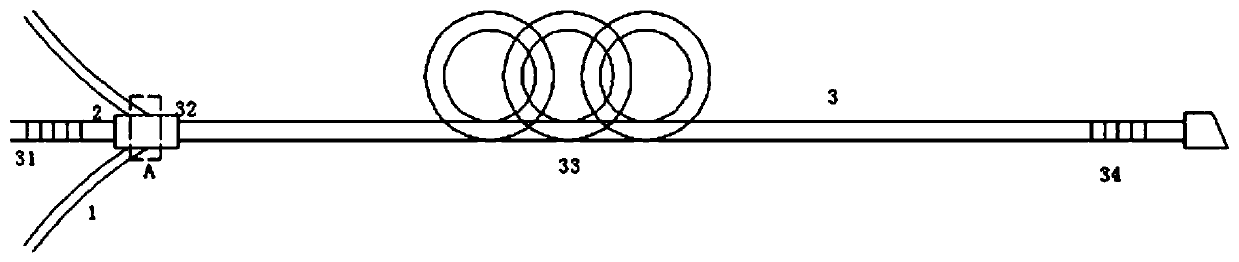
[0039] Such as figure 1 with Image 6As shown, this embodiment discloses a high-stability fiber laser, comprising a first fiber grating (31), a beam combiner (32), a gain fiber (33), and a second fiber grating (34) arranged in sequence, wherein :

[0040] A resonant cavity (3) composed of a first fiber grating (31) and a second fiber grating (34), the gain fiber (33) is arranged on the first fiber grating (31) and the second fiber grating (34) between;

[0041] The pump fiber (1) and the signal fiber (2) are side-fused to form a beam combiner (32), and the beam combiner (32) is arranged between the first fiber grating (31) and the gain fiber (33), so The gain fiber (33) is fused with the signal fiber.

[0042] After a section of the pumping fiber (1) removes the first coating layer (13), it is heated and pre-tapered to form a first tapered section, a connecting section and a second tapered section, the first tapered section, the connecting section It is connected with the...

Embodiment 2

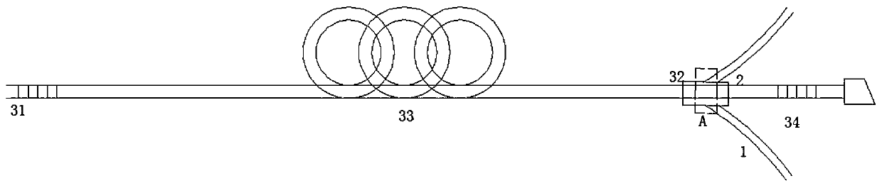
[0050] Such as figure 2 As shown, this embodiment discloses a high-stability fiber laser. The difference from Embodiment 1 is that the fiber laser disclosed in this embodiment includes a first fiber grating (31), a gain fiber (33), a Beam combiner (32), the second fiber grating (34), wherein:

[0051] A resonant cavity (3) composed of the first fiber grating (31) and the second fiber grating (34), the beam combiner (32) is arranged between the gain fiber (33) and the second fiber grating (34), the The pumping optical fiber (1) coupled in the beam combiner (32) is used to reversely provide pumping light.

Embodiment 3

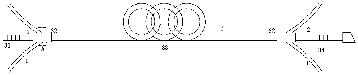
[0053] Such as image 3 As shown, this embodiment discloses a high-stability fiber laser. The difference from Embodiment 1 is that the fiber laser disclosed in this embodiment includes a first fiber grating (31) and a beam combiner (32) arranged in sequence. , gain fiber (33), beam combiner (32) and second fiber grating (34), wherein:

[0054] A resonant cavity (3) composed of a first fiber grating (31) and a second fiber grating (34), the gain fiber (33) is arranged on the first fiber grating (31) and the second fiber grating (34) between;

[0055] A beam combiner (32) is respectively arranged between the first fiber grating (31) and the gain fiber (33), between the gain fiber (33) and the second fiber grating (34), and the pump fiber (1) and the signal fiber (2) are coupled in a beam combiner (32), and the pumping fiber (1) coupled in the beam combiner (32) on both sides of the gain fiber (33) is used to provide pumping light bidirectionally .

[0056] The gain fiber (33...


PUM


Abstract

The invention discloses a high-stability optical fiber laser comprising a beam combiner arranged in a resonant cavity. The first conical section of the pumped fiber and the coupling region on the signal fiber are fused and coupled to form the beam combiner. The gain fiber in the resonant cavity absorbs the pump light transmitted by the pumped fiber into the resonant cavity through the beam combiner so as to form laser to be outputted. The beam combiner is arranged in the resonant cavity so that the excessively high power pump light can be prevented from being directly injected into the fiber grating, the stability of the laser can be enhanced and the single resonant cavity laser is enabled to output the laser of higher power. Compared with the end surface pump technology, the pump fiber and the side surface of the signal fiber are fused and coupled and the signal insertion loss is almost zero so that the pump efficiency can be greatly enhanced, the heat generated in coupling can be significantly reduced, the optical-to-optical conversion efficiency of the laser can be enhanced, high power output of the optical fiber laser can be guaranteed and the stability of the optical fiber laser can be further enhanced.

Description

technical field [0001] The invention relates to the field of fiber lasers, in particular to a high-stability fiber laser. Background technique [0002] The pump coupler is an important device used in fiber lasers and fiber amplifiers. It can guide single or multiple LD pump lights into the fiber through the pump fiber without affecting the transmission of the main optical path to provide the required power for the laser. The advantage of the pump power. [0003] The manufacturing process of the existing pump coupler products is generally to taper the fiber bundle composed of the intermediate signal optical fiber and the surrounding pump fiber until the diameter of the taper waist is the same as that of the double-clad fiber. Cut off at the end and perform fusion splicing with the double-clad optical fiber. For example, ZL201410224237.8 discloses a (N+1)×1 fiber end-face pumping beam combiner based on optical fiber erosion. The signal input optical fiber disclosed in this p...

Claims


Application Information

Patent Timeline
Patent Type & Authority Patents(China)
IPC IPC(8): H01S3/094H01S3/067
CPCH01S3/06716H01S3/094003H01S3/094019H01S3/094053
Inventor 梁小宝李琦孙梦至
Owner 四川思创激光科技有限公司
Why Eureka
Try Eureka