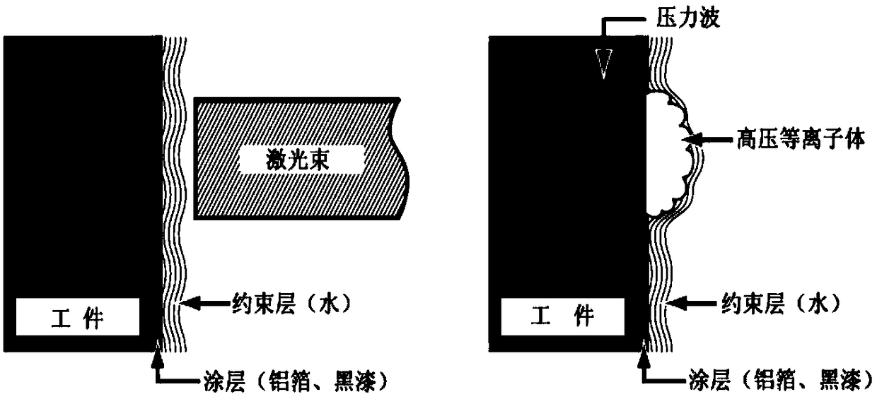
Method of absorbing shock waves of nanosecond impulse laser shock strengthened titanium alloy thin blade
A nanosecond pulse laser and shock strengthening technology, which is applied in the field of nanosecond pulse laser shock strengthening titanium alloy thin blade shock wave absorption, can solve the macro deformation of thin blades, do not meet the design and use requirements, and it is difficult to form a uniform gradient residual compressive stress field and other issues, to achieve the effect of simple operation and high feasibility
- Summary
- Abstract
- Description
- Claims
- Application Information
AI Technical Summary
Problems solved by technology
Method used
Image

Examples
Embodiment Construction
[0035] The preferred embodiments of the present invention will be described below in conjunction with the accompanying drawings. It should be understood that the preferred embodiments described here are only used to illustrate and explain the present invention, and are not intended to limit the present invention.
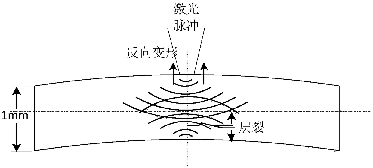
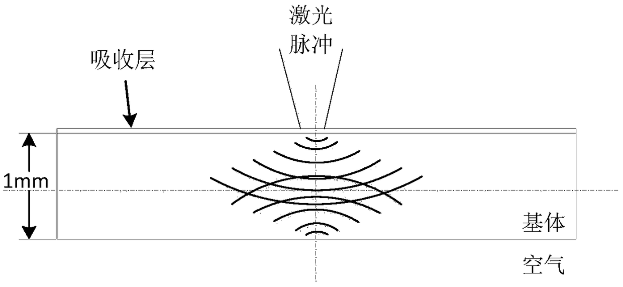
[0036] Example: Refer to the schematic Figure 5 , Design and manufacture shock wave absorbing device. (a) Establish the finite element model of waveguide material as image 3 As shown, the model is divided into upper and lower layers. The upper layer is a titanium alloy thin plate, and the lower layer is a waveguide material that matches the impedance of the titanium alloy plate to verify the feasibility of wave penetration. The numerical simulation results are as follows: Figure 7 , The shock wave absorbing device can achieve 80% wave transmission, but there are still some reflections on the back.
[0037] (b) Fabrication of impedance-matching elastomers. The ...
PUM
| Property | Measurement | Unit |
|---|---|---|
| thickness | aaaaa | aaaaa |
Abstract
Description
Claims
Application Information
PatSnap Eureka turns technology decisions into work you can execute. Powered by our Innovation Knowledge Graph, it runs expert workflows across engineering, life sciences, materials and intellectual property. Get your review-ready output in minutes.


