Nano-scale high-precision additive manufacturing equipment

An additive manufacturing and high-precision technology, applied in the field of additive manufacturing, can solve the problems of difficulty in pulling ultra-fine droplets, inaccurate deposition of droplets, and limited printing accuracy, avoiding complex secondary weaving and small gaps. , Improve the effect of printing accuracy

Pending Publication Date: 2018-11-06
CENT SOUTH UNIV
View PDF3 Cites 18 Cited by
  • Summary
  • Abstract
  • Description
  • Claims
  • Application Information

AI Technical Summary

Problems solved by technology

But there are still the following deficiencies: first, the mobile platform used is a stepper motor with poor precision, without a grating ruler, and the positioning error reaches more than 20 microns
Third, when using the printing mode driven by air pressure, there will be a huge delay at the moment of stopping, and the printing liquid will still be squeezed out after stopping the air pressure
Fourth, the charged droplet will have a spiral lateral movement tendency (as shown in the figure) driven by high voltage, which will cause the dropped droplet to not be accurately deposited on the target position, and the error will be large, which will affect the accuracy, thus greatly limits the application of the technology
With this technology, the greater the distance the droplet travels in the magnetic field, the greater the deflection, and the accuracy cannot be controlled
The patent number is CN201620744062.8 Chinese utility model patent, which discloses a 3D printing device based on electromagnetic emission technology. This patent is similar to patent CN201620744062.8. The charged droplet reaches the target point
However, the magnetic field force is weak for the driving force of charged droplets, it is difficult to pull out ultra-fine droplets, and the printing accuracy is limited. It is mainly used for biomaterial printing.

Method used


Image

  • Nano-scale high-precision additive manufacturing equipment
  • Nano-scale high-precision additive manufacturing equipment
  • Nano-scale high-precision additive manufacturing equipment

Examples


Embodiment Construction

[0046] The present invention will be further described below in conjunction with the accompanying drawings and specific embodiments.

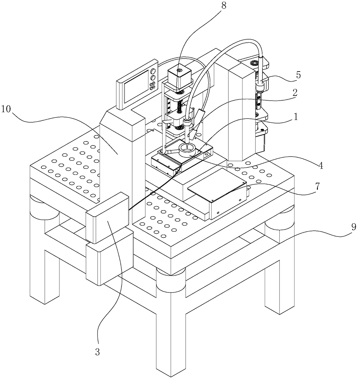
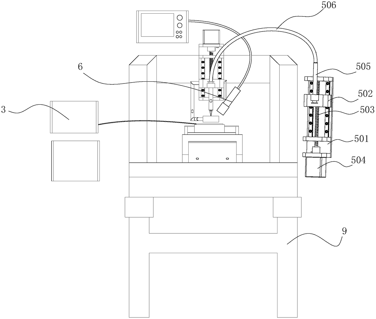
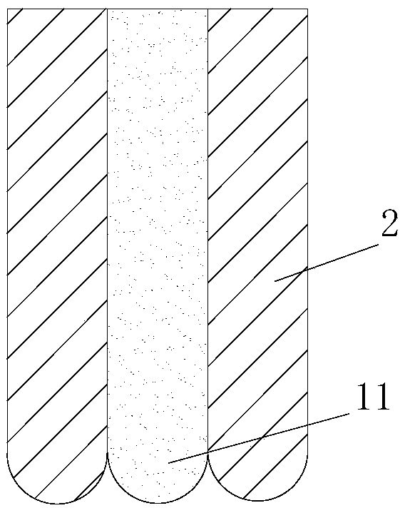
[0047] see figure 1 and figure 2 , in one embodiment, the nanoscale high-precision additive manufacturing equipment includes a printing platform 1 and a printing nozzle 2, the printing nozzle 2 is arranged above the printing platform 1 and the nozzle is facing the printing platform 1, and the conductive nozzle of the printing nozzle 2 A high-voltage pulse power supply is applied between the printing platform 1. There is also a uniform magnetic field (not shown in the figure) perpendicular to the printing platform between the printing platform 1 and the printing nozzle 2, the direction of the magnetic field line is facing the printing platform 1, and the distance D between the printing platform 1 and the printing nozzle 2 satisfies the following relationship Mode:

[0048] D=N×T×V 平

[0049] in,

[0050] m is the mass of each drop of pr...


PUM

PropertyMeasurementUnit
surface roughnessaaaaaaaaaa

Abstract

The invention discloses nano-scale high-precision additive manufacturing equipment. The nano-scale high-precision additive manufacturing equipment comprises a printing platform and a printing nozzle,wherein a high-voltage pulse power supply is applied between the printing platform and a conductive nozzle of the printing nozzle; and a uniform-intensity magnetic field perpendicular to the printingplatform is further arranged between the printing platform and the printing spray head, and the distance between the printing platform and the printing nozzle meets the characteristic requirements. According to the nano-scale high-precision additive manufacturing equipment, nano-scale 2D and 3D additive manufacturing is achieved, high-voltage pulse electric fluid dynamic jetting, a nano-scale printing head and a constraint magnetic field are benefited, and the problem that high-precision nano-scale materials cannot be constructed in the prior art is solved, and particularly relates to the insufficiency and restrictions in the field of electronic circuit board printing, nano energy storage, solar cells and biomedicine, flexible electronic materials, high-flux preparation and the like.

Description

technical field [0001] The invention belongs to the technical field of additive manufacturing, and in particular relates to a nanoscale high-precision additive manufacturing equipment. Background technique [0002] In the field of electronic printing, with the miniaturization of electronic components, the requirements for the fineness of electronic printing are getting higher and higher, such as circuit boards, touch screens, biosensors, RFID antennas, and primary battery fingerprint photography. The use of screen printing for thin lines below 70 μm may be limited by the screen itself, and on the other hand, it will also be limited by the printing paste. The limitation of the screen is mainly the mesh number of the screen and the thickness of the mesh, while the limitation of the printing paste is the particle size, viscosity and rheological properties of the printing paste. Although these factors can be optimized, there are many factors that will affect the pioneering acti...

Claims


Application Information

Patent Timeline
Patent Type & Authority Applications(China)
IPC IPC(8): B29C64/106B29C64/205B29C64/209B29C64/245B29C64/30B33Y30/00B33Y40/00
CPCB29C64/106B29C64/205B29C64/209B29C64/245B29C64/30B33Y30/00B33Y40/00
Inventor 刘军张睿智黄靖栋
Owner CENT SOUTH UNIV
Why Eureka
Try Eureka