
Hot-blast stove chamber, drying system and drying method

A hearth and hot air technology, which is applied in the direction of drying, drying machine, heating to dry solid materials, etc., can solve the problems of limited design size, low heat exchange efficiency, waste, etc., to reduce heat loss and waste, and increase contact area , the effect of reducing energy loss

Pending Publication Date: 2018-11-06
FUJIAN TIETUO MACHINERY
View PDF0 Cites 7 Cited by
  • Summary
  • Abstract
  • Description
  • Claims
  • Application Information

AI Technical Summary

Problems solved by technology

[0003] 1. Due to the relatively low temperature of medium-temperature hot air used as the heating medium, the heat exchange efficiency is relatively low, resulting in relatively low equipment capacity;
[0004] 2. The dimensions and specifications of each type of drying drum and hot blast furnace are generally designed according to the requirements of the maximum output and are fixed. Moreover, due to cost and site constraints, the design size of the drying drum is often limited, so In the fixed and limited heat exchange area, it is impossible to make flexible adjustments in time according to the change of production output, resulting in the loss and waste of heat energy (energy)

Method used


Image

  • Hot-blast stove chamber, drying system and drying method
  • Hot-blast stove chamber, drying system and drying method
  • Hot-blast stove chamber, drying system and drying method

Examples


Embodiment 1

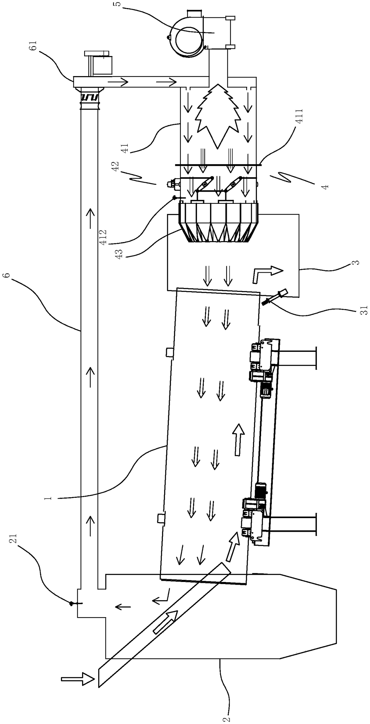
[0031] Embodiment one, with reference to Figure 1 to Figure 4 As shown, a countercurrent waste asphalt drying system includes a drying drum 1 arranged obliquely, a feed box 2 arranged at the high end of the drying drum 1, a discharge box 3 arranged at the low end of the drying drum 1, and a connecting outlet The hot-blast hearth 4 of the material box 3, the burner 5 connected to the hot-blast hearth 4, the return air duct 6 connected between the hot-blast furnace 4 and the feed box 2, the induced draft fan 61 arranged on the return air duct 6, The tail gas temperature sensor 21 on the top of the material box 2 , the furnace temperature sensor 412 arranged on the hot blast furnace 4 , and the discharge temperature sensor 31 arranged on the discharge box 3 .

[0032] The exhaust gas inside the feed box 2 is sent back to the hot blast furnace 4 through the return air duct 6, and the high-temperature flame ejected from the burner 8 is fully mixed and burned in the hot blast furna...

Embodiment 2

[0037] Embodiment two, refer to figure 2As mentioned above, it is a downstream waste asphalt drying system, which includes a drying drum 91 arranged obliquely, a feed box 93 arranged at the high end of the drying drum 91, a discharge box 92 arranged at the low end of the drying drum 91, and an inlet Material box 93 communicates with hot blast hearth 94, burner 95 connected with hot blast hearth 94, return air duct 96 that is connected between hot blast hearth 94 and discharge box 92, induced draft fan 961 that is arranged on the return air duct 96, is arranged on outlet The tail gas temperature sensor 921 at the top of the material box 92, the discharge temperature sensor 922 arranged at the bottom of the discharge, and the furnace temperature sensor 941 arranged at the hot blast furnace 94, the specific structure of the hot blast furnace 94 is the same as that of the first embodiment.

[0038] A method for drying waste asphalt, using the above-mentioned drying system, specif...


PUM


Abstract

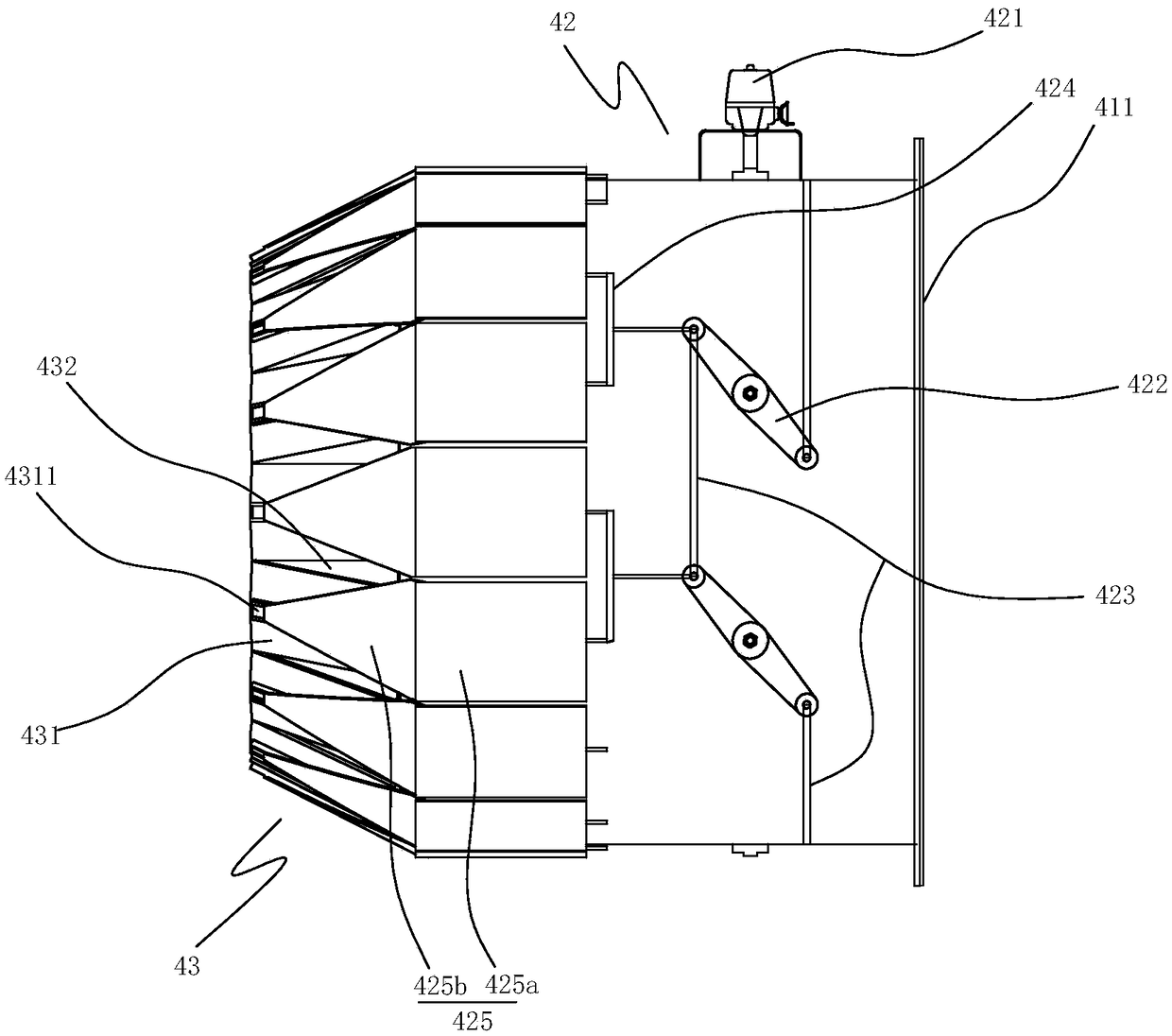
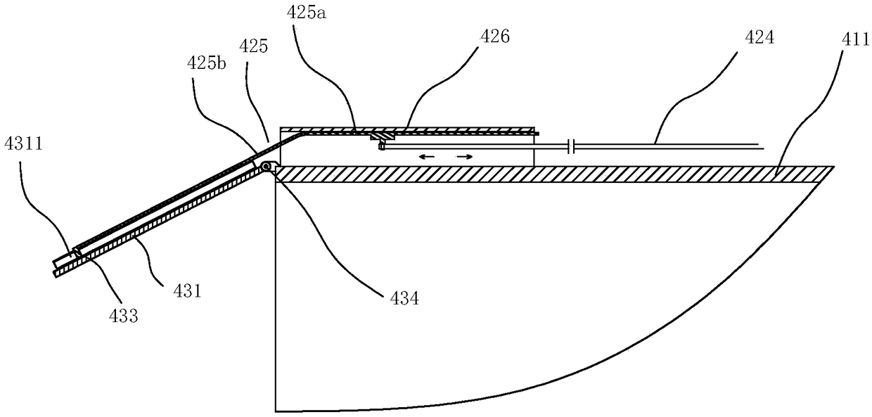
The invention provides a hot-blast stove chamber, a drying system and a drying method. The hot-blast stove chamber comprises a stove chamber body, an air outlet and a driving mechanism; the air outletcomprises a plurality of rotating blades; the multiple rotating blades are circumferentially arrayed and are rotatably arranged on the stove chamber body; the multiple rotating blades surround to form a conical air outlet; and the driving mechanism is connected with the multiple rotating blades and drive the multiple rotating blades to synchronously rotate so as to adjust the diameter of the airoutlet. The diameter of the air outlet is adjusted, so that the effect that the flow rate of hot air blown by the air outlet of the stove chamber is adjusted in time under the condition that equipmenthas different yields is achieved flexibly, the energy utilization rate is increased, and energy conservation and emission reduction are achieved.

Description

technical field [0001] The invention relates to a hot blast furnace, a drying system and a drying method, and is mainly used in a waste asphalt drying and heating system. Background technique [0002] Asphalt mixture thermal regeneration technology is a technology to recycle waste asphalt mixture. After the waste asphalt mixture is sent to the drying heating system for drying and heating treatment, it is then mixed with a certain proportion of new asphalt mixture. In the existing thermal regeneration technology, heating methods can generally be divided into direct heating by high-temperature flame heat radiation and indirect heating by medium-temperature hot air. Among them, in order to reduce the asphalt on the surface of waste asphalt mixture during The degree of aging is often indirectly heated by medium-temperature hot air. However, the method of indirect heating with medium-temperature hot air currently has the following problems: [0003] 1. Due to the relatively low...

Claims


Application Information

Patent Timeline
IPC IPC(8): F24H9/00F26B21/14F26B21/12F26B11/04F26B3/06
CPCF24H9/0052F26B3/06F26B11/04F26B21/12F26B21/14
Inventor 潘泽源党森纪
Owner FUJIAN TIETUO MACHINERY
Learn More