Reactive sintering Cf/SiC composite material and synchronous reaction connection method

A composite material and connecting layer technology, which is applied in the field of organic resin carbon source and online connection process to realize Cf/SiC composite material connection, can solve the problems of material deformation, adverse effect of composite material connection performance, cracking, etc. Excellent high temperature performance and good thermal property matching effect

Inactive Publication Date: 2018-11-13
SHANGHAI INST OF CERAMIC CHEM & TECH CHINESE ACAD OF SCI
View PDF10 Cites 2 Cited by
  • Summary
  • Abstract
  • Description
  • Claims
  • Application Information

AI Technical Summary

Problems solved by technology

C as described in the prior art f / SiC composite material connection method is C f After the SiC material is prepared, it is connected, and the connection process is carried out at high temperature, so that the

Method used


Image

  • Reactive sintering Cf/SiC composite material and synchronous reaction connection method
  • Reactive sintering Cf/SiC composite material and synchronous reaction connection method
  • Reactive sintering Cf/SiC composite material and synchronous reaction connection method

Examples


Embodiment 1

[0032] A reaction sintering C f / SiC composite material synchronous reaction connection method, comprising the following steps:

[0033] 1) Preparation of resin-based slurry:

[0034] a. Prepare raw materials according to the following ratio:

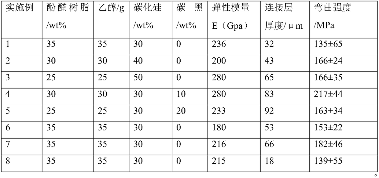
[0035] 35% of phenolic resin, 35% of ethanol, 30% of silicon carbide micropowder; The particle size is 0.5 μm.

[0036] b. Add ethanol to the phenolic resin, stir to fully dissolve it, and configure the phenolic resin solution;

[0037] c. adding silicon carbide micropowder to the phenolic resin solution to form a slurry;

[0038] d. Add polyvinylpyrrolidone as a dispersant, then ball mill the slurry for 12 hours, and vacuum degass it for 2 hours to obtain a binder.

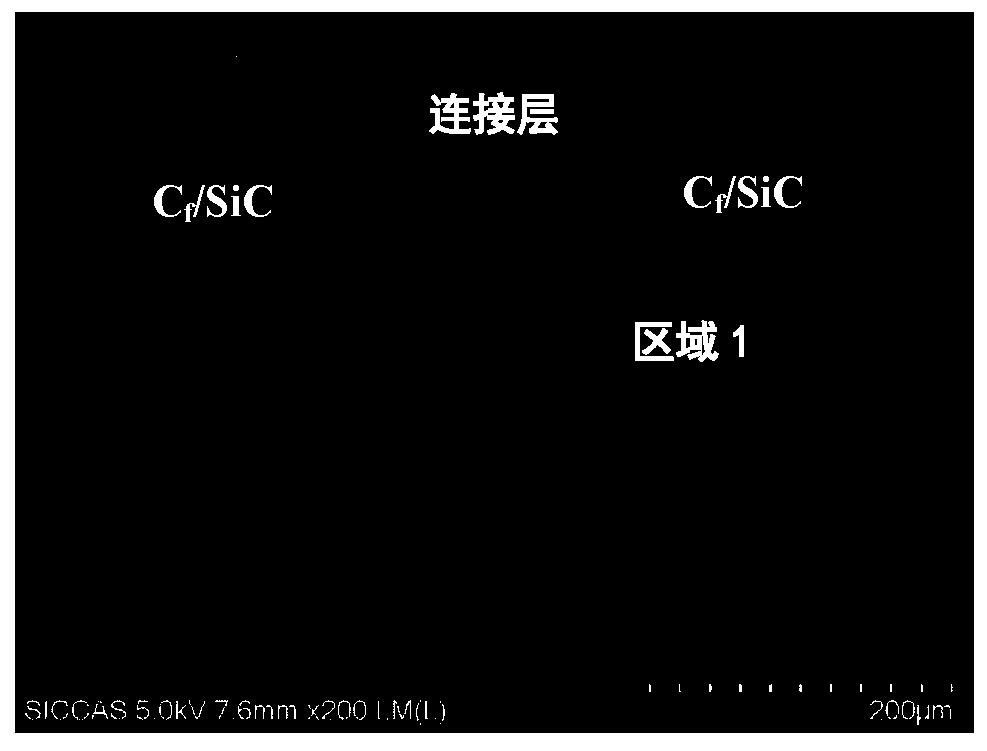
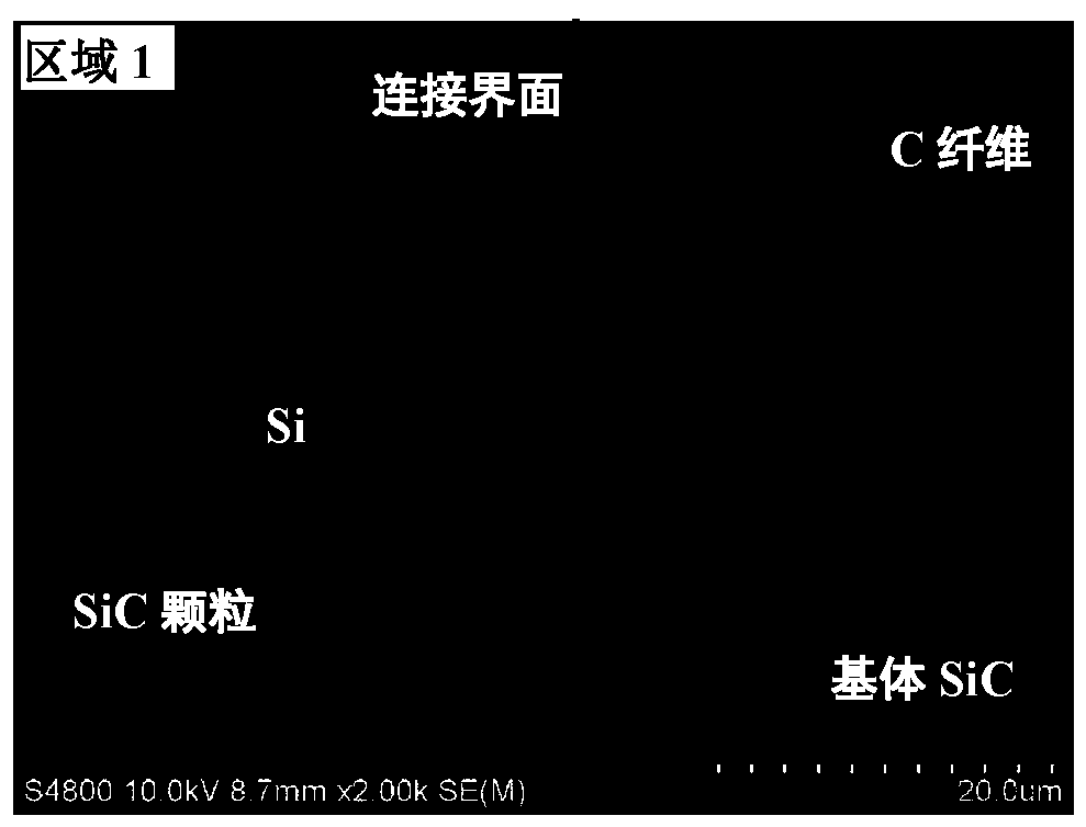
[0039] 2) Preparation of parts to be connected: prepare at least two reaction sintering C f / SiC process without SiC f / C material is used as the part to be connected, and the surface to be connected is ground with a grinder to remove impurities on the surface to be...

Embodiment 2

[0043] In this embodiment, it is basically the same as Example 1, the difference is:

[0044] Prepare resin-based slurry in step 1):

[0045] a. 30% phenolic resin, 30% ethanol, 40% silicon carbide micropowder; and, the dispersant polyvinylpyrrolidone with 4% of the main component by weight, and the curing agent with 4% of the main component by weight; wherein, silicon carbide The particle size of the fine powder is 1 μm.

Embodiment 3

[0047] In this embodiment, it is basically the same as Example 1, the difference is:

[0048] Preparation of resin-based slurry in step 1): as a carbon source in the binder and reactive siliconizing process:

[0049] a. Prepare raw materials according to the following ratio:

[0050] 25% of phenolic resin, 25% of ethanol, 50% of silicon carbide micropowder; and, the dispersant polyvinylpyrrolidone of 4% of the main component by weight, and the curing agent of 4% of the main component by weight; wherein, silicon carbide micropowder The particle size is 0.5 μm.


PUM

PropertyMeasurementUnit
Thicknessaaaaaaaaaa

Abstract

The invention relates to a reactive sintering Cf/SiC composite material and a synchronous reaction connection method. The method includes: coating precursor slurry of carbon between connection faces of at least two Cf/C porous precursor to-be-connected members, and curing to form a porous carbon based connection layer to obtain a pre-connector, wherein main ingredients of the precursor slurry of carbon include 25-55wt% of carbon source, 25-35wt% of solvent and 20-50wt% of silicon carbide powder, and the carbon source is an inorganic carbon source or/and an organic carbon source; performing liquid-phase siliconizing on the pre-connector at 1450-1650 DEG C to synchronously complete preparation and connection of the Cf/SiC composite material. The production process is simplified, deformationand cracking risks caused in the process of repeated high-temperature treatment are lowered, and preparing of the Cf/SiC composite material more complex in shape and large in size is better facilitated.

Description

technical field [0001] The invention relates to a method for reaction sintering C f / SiC composite material online reaction connection method, specifically design a carbon source through organic resin and online connection process to realize C f / SiC composite material connection method. Background technique [0002] Compared to SiC ceramics, C f The unique energy dissipation mechanisms such as crack deflection, fiber pull-out, and bridging of SiC composites make it exhibit non-catastrophic failure characteristics similar to metals, thereby greatly improving its reliability in engineering applications. In addition, C f / SiC combines the advantages of high temperature resistance, corrosion resistance, high specific stiffness, high thermal conductivity, and low density of SiC ceramics and carbon fibers. Therefore, C f / SiC composite materials are widely used in aerospace, military, energy and other fields as high-temperature structural materials. However C f The high we...

Claims


Application Information

Patent Timeline
IPC IPC(8): C04B37/00C04B35/80C04B35/84C04B35/565
CPCC04B35/806C04B35/573C04B37/005C04B2235/3826C04B2235/428C04B2235/5248C04B2237/083C04B2237/55C04B2237/78
Inventor 黄政仁吴西士朱云洲殷杰姚秀敏刘泽华陈健刘岩
Owner SHANGHAI INST OF CERAMIC CHEM & TECH CHINESE ACAD OF SCI
Why Eureka
Try Eureka