A photobiological reaction device that can effectively absorb and utilize exhaust gas

A photobioreaction and effective absorption technology, applied in photobioreactors, specific-purpose bioreactors/fermenters, biochemical cleaning devices, etc. Difficult to control the cultivation conditions and other problems, to achieve the effect of improving the photobiological reaction rate, promoting the circulation and flow of materials, and improving the utilization rate of light.

Active Publication Date: 2020-06-23
CHONGQING UNIV
View PDF6 Cites 0 Cited by
  • Summary
  • Abstract
  • Description
  • Claims
  • Application Information

AI Technical Summary

Problems solved by technology

[0004] However, the open culture system has insurmountable shortcomings such as difficult to control the culture conditions, seasonal control of the production cycle, easy to be polluted, and a large amount of evaporation of the culture medium, so the culture efficiency and the added value of the product are low.

Method used


Image

  • A photobiological reaction device that can effectively absorb and utilize exhaust gas

Examples


Embodiment 1

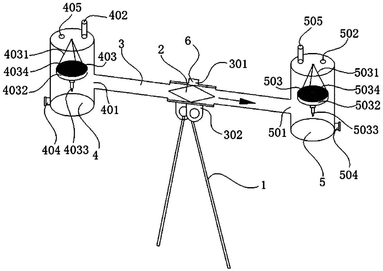
[0065] Such as figure 1 As shown, a photobioreaction device that can effectively absorb and utilize exhaust gas is characterized in that it mainly includes a support column 1, a flow plug 2, a hollow shaft 3, a transparent photobioreactor container A4 and a transparent photobioreactor container B5.

[0066] The hollow rotating shaft 3 is a tubular structure with both ends open and a hollow inside. The hollow rotating shaft 3 is a reducing pipe, the diameter of the hollow rotating shaft 3 in the middle is D, and the diameter of the pipes at both sides is d, where D>d.

[0067] When the hollow rotating shaft 3 is placed parallel to the ground, an opening 301 is provided at the top of the outer wall at the middle position of the hollow rotating shaft 3 , and a base 302 is provided at the bottom end of the outer wall at the middle position.

[0068] The hollow rotating shaft 3 is connected with the support column 1 through the base 302 . Both sides of the hollow rotating shaft 3...

Embodiment 2

[0106] Experiment using the device in Example 1;

[0107] A flue gas inlet valve 6 is arranged above the center of the hollow rotating shaft 3, and the exhaust gas discharged from the gas turbine or other smoke exhaust equipment during operation mainly includes CO 2 and H 2 O enters the hollow shaft 3 through the flue gas inlet valve 6;

[0108] When the hollow rotating shaft 3 is kept horizontal, the flow plug 2 is also kept horizontal and does not block any channel opening at either end of the hollow rotating shaft 3, and the exhaust gas can smoothly enter the transparent photobioreaction container A4 connected to the two ends of the hollow rotating shaft 3 through the channel openings on both sides And in the transparent photobioreactor container B5, in the horizontal reactor I403 and the horizontal reactor II503 in the transparent photobioreactor container A4 and the transparent photobioreactor B5, there are photoreactive organisms I4034 and photoreactive biological II503...


PUM


Abstract

The invention discloses a photo-biological reaction device capable of effectively absorbing and utilizing tail gas. The device is characterized in that tail gas is sufficiently absorbed and utilized through a photo-biological reactor, so that liquid substances such as bio-oil and the like are produced; energy of a light source is sufficiently utilized, and the light utilization rate and the photo-biological reaction rate are increased; by use of a flow plunger, tail gas introduced into a hollow rotating shaft is subjected to two-way non-equivalent conveying, and due to change of reaction quality in transparent photo-biological reaction containers, vertical movement in the vertical surface of the hollow rotating shaft is realized; the liquid substances such as bio-oil and the like obtainedthrough photo-biology can be recycled; through equal-length connecting lines connecting a horizontal reaction kettle and the transparent photo-biological reaction containers, the horizontal reaction kettle is slightly shaken and finally kept horizontal; through a constant-pressure valve nozzle, dynamic stability and controllable function of photo-biological and photo-physiological reactions in thetransparent photo-biological reaction containers are realized, constant pressure of the photo-biological and photo-physiological reactions in the transparent photo-biological reaction containers is guaranteed, and the photo-biological reaction substance utilization rate in the transparent photo-biological reaction containers is increased.

Description

technical field [0001] The invention relates to the field of photobiological reaction devices, in particular to a photobiological reaction device capable of effectively absorbing and utilizing tail gas. Background technique [0002] Research on photobioreactors began in the 1940s, when the goal was to cultivate microalgae in large quantities, and its main purpose was to explore the feasibility of microalgae as human food protein and fuel resources in the future. [0003] Since the 1950s, people have developed a variety of closed photobioreactors such as horizontal tubes, vertical tubes and flexible tubes. The open reactor has been well developed because of its advantages of simple technology, low investment, easy construction and easy operation, and has been successfully used in large-scale cultivation of spirulina and chlorella with good results. [0004] However, the open culture system has insurmountable shortcomings such as difficult to control the culture conditions, s...

Claims


Application Information

Patent Timeline
Patent Type & Authority Patents(China)
IPC IPC(8): C12M1/04C12M1/36C12M1/00B01D53/84B01D53/62
CPCB01D53/62B01D53/84B01D2257/504C12M21/02C12M27/02C12M27/18C12M29/24C12M31/08C12M41/34C12M41/40Y02A50/20
Inventor 谢尹周永利孔繁臣范啸宇张力元李友荣孙宽王国强卞煜李猛王露
Owner CHONGQING UNIV
Why Eureka
Try Eureka