Multi-layer net shaped staggered rib plate type hydrogen storage reaction device

The technology of a reaction device and a rib plate is applied in the direction of tubular elements, heat exchange equipment, fixed tubular conduit components, etc., and can solve the problems of inability to promote large-scale industrial applications, complicated processing technology of heat exchangers, and inability to popularize and use in large quantities. Achieve the effect of compact structure, small gas phase diffusion resistance and convenient maintenance

Active Publication Date: 2018-11-20
安徽秉品新能源科技有限公司
View PDF5 Cites 7 Cited by
  • Summary
  • Abstract
  • Description
  • Claims
  • Application Information

AI Technical Summary

Problems solved by technology

The reactor has compact structure, fast reaction speed, and high heat exchange efficiency. However, due to the placement of multiple thin annular fins on the thin heat exchange pipes, the processing technology of the heat exchanger is complicated and the cost is high, which is not conducive to large-scale use.
[0008] Other forms of hydrogen storage reactors: such as U-shaped tube type, honeycomb type, and bow-shaped plate type hydrogen storage reactors, have the characteristics of compact structure, convenient operation, and fast reaction speed, but due to the general heat transfer effect and difficult processing, they cannot be extended to large-scale applications. In large-scale industrial applications
[0009] It can be seen that there are some defects in the above-mentioned existing hydrogen storage reactors, and they cannot be popularized and used in large-scale industrial applications.

Method used


Image

  • Multi-layer net shaped staggered rib plate type hydrogen storage reaction device
  • Multi-layer net shaped staggered rib plate type hydrogen storage reaction device
  • Multi-layer net shaped staggered rib plate type hydrogen storage reaction device

Examples


Embodiment Construction

[0032] The technical solution of the present invention will be further described below in conjunction with the accompanying drawings and specific embodiments.

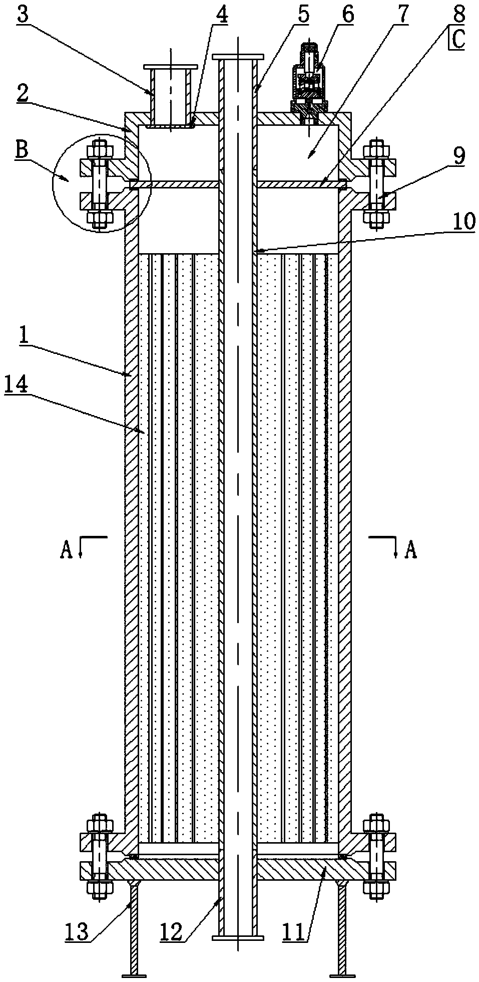
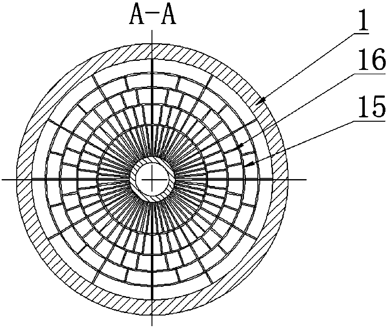
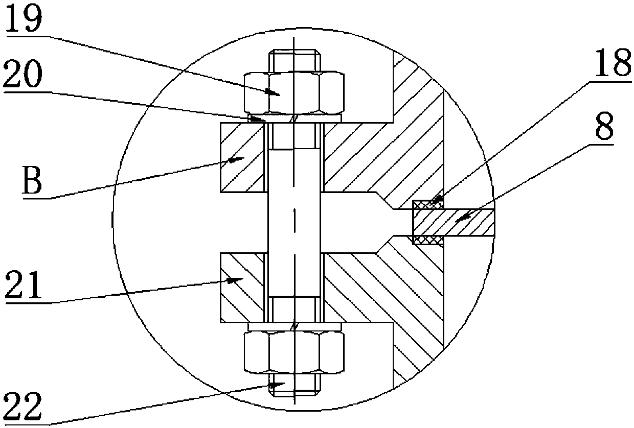
[0033] The invention provides a hydrogen storage reaction device with multi-layer mesh interlaced ribs, the device is a vertical structure, such as figure 1 As shown, the housing 1 is included, and the upper and lower ends of the housing 1 are respectively sealed and connected with an upper head 2 and a lower head 11 through a flange structure 9 . Wherein, a heat exchange tube 10 is arranged at the center of the housing 1, and multi-layer circumferential ribs 15 are sequentially arranged between the inner wall of the housing 1 with the heat exchange tube 10 as the center, and the heat exchange tube 10 and the housing are connected. 1 The space between the inner walls is divided into a plurality of reaction areas, and the area of ​​each reaction area is equal, and a reaction vehicle layer 14 is arranged in the reaction ...


PUM


Abstract

The invention discloses a multi-layer net shaped staggered rib plate type hydrogen storage reaction device. The device is of a three-dimensional structure and comprises a housing, wherein the upper end and the lower end of the housing are correspondingly connected to an upper sealing head and a lower sealing head through flange structures in a sealing manner; a heat exchanging pipe is arranged inthe center of the housing; a plurality of layers of circumferential rib plates are sequentially arranged at the outer part of the heat exchanging pipe; a radial rib plate is arranged between two adjacent layers of circumferential rib plates; a reaction bed layer is arranged in each of the spaces formed by the radial rib plates and the circumferential rib plates; a tubular plate is arranged betweenthe upper sealing head and the housing, and an air phase buffering chamber is formed between the tubular plate and the upper sealing head; a heat exchanging liquid inlet which communicates with the heat exchanging pipe, an air phase inlet which is connected to the air phase buffering chamber and an air safety valve are arranged on the upper sealing head. The device is applicable to high reactionheat effect chemical reaction such as dehydrogenation or hydrogenation of metal hydride. The device has the advantages of being high in heat transfer rate, simple to operate, compact in structure, andconvenient to maintain.

Description

technical field [0001] The invention belongs to the technical field of chemical reaction devices; in particular, it relates to the technical field of hydrogenation or dehydrogenation reactions; in particular, it relates to a hydrogen storage reaction device with multi-layer network interlaced ribs. Background technique [0002] At present, there are mainly the following types of hydrogen storage reactors at home and abroad for the large thermal effect in the hydrogenation / dehydrogenation reaction process: [0003] Fixed bed hydrogen storage reactor: It includes a cylindrical shell with a reaction chamber inside, filled with solid metal hydride, the reaction gas enters from the top of the chamber, and a heat exchange fluid is arranged around the chamber. Heat exchange during hydrogenation / dehydrogenation. The reactor has the characteristics of simple structure and low cost, but because the reaction chamber is filled with less metal hydride, the complete diffusion of hydrogen...

Claims


Application Information

Patent Timeline
Patent Type & Authority Applications(China)
IPC IPC(8): B01J19/00F28D7/00F28F1/30
Inventor 杨福胜申传健张早校张诗伟张洋
Owner 安徽秉品新能源科技有限公司
Why Eureka
Try Eureka