

Online monitoring method for laser additive manufacturing
A laser additive and laser power technology, which is applied in the field of additive manufacturing, can solve the problems that the quality requirements of laser additive manufacturing are difficult to meet, and achieve the effect of avoiding difficult operation
- Summary
- Abstract
- Description
- Claims
- Application Information
AI Technical Summary
Problems solved by technology
Method used
Image

Examples
Embodiment 1
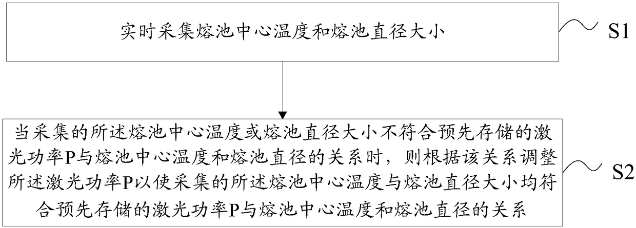
[0074] An online monitoring method for laser additive manufacturing containing a ceramic reinforced phase coating, comprising the following steps:
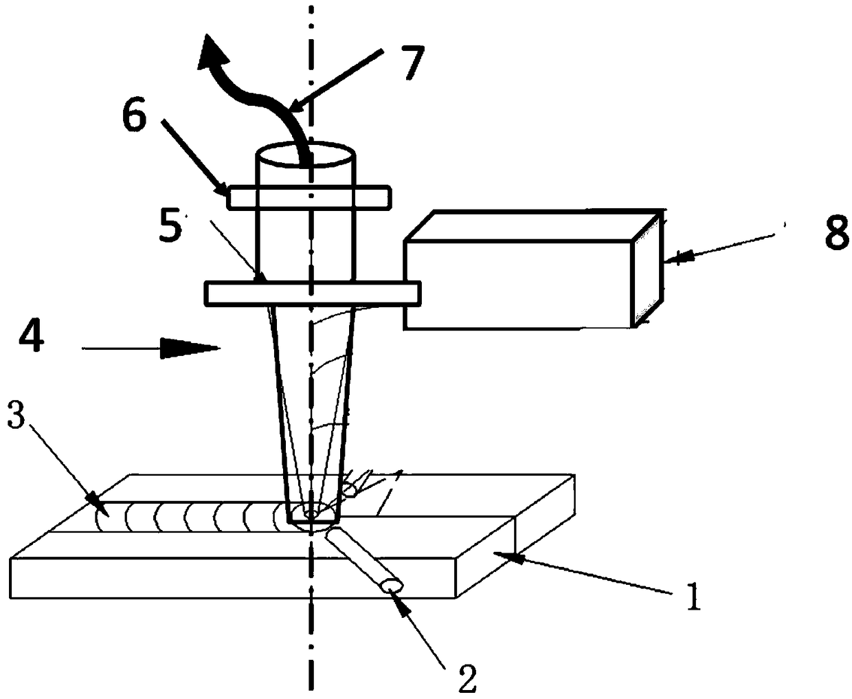
[0075] S1: Install and set up each device; specifically, multi-wavelength pyrometer, CCD high-speed infrared camera, laser processing head, laser power detector (with feedback and detection functions, used for power measurement and feedback, and automatic adjustment of power), CCD high-speed camera and protective gas pipeline are installed and set up according to the requirements;
[0076] S2: The test sample is placed at the designated position; here, Fe-based stainless steel powder is selected, and additive manufacturing is carried out on the Fe-based stainless steel 316L substrate. The strengthening phase is WC, and the proportion of WC in the strengthening phase is 2.5%, 5% and 10%. The method of feeding powder is adopted. The WC and Fe-based powders are uniformly mixed using a ball mill.
[0077] S3: Fixed laser scanning sp...
Embodiment 2
[0087] In this embodiment, the powder used is Ni-based alloy In625, the experimental substrate is 316 stainless steel, and the strengthening phase is TiC powder. The content of TiC in the period is 10%, 20%, 30%, and the difference with embodiment one is
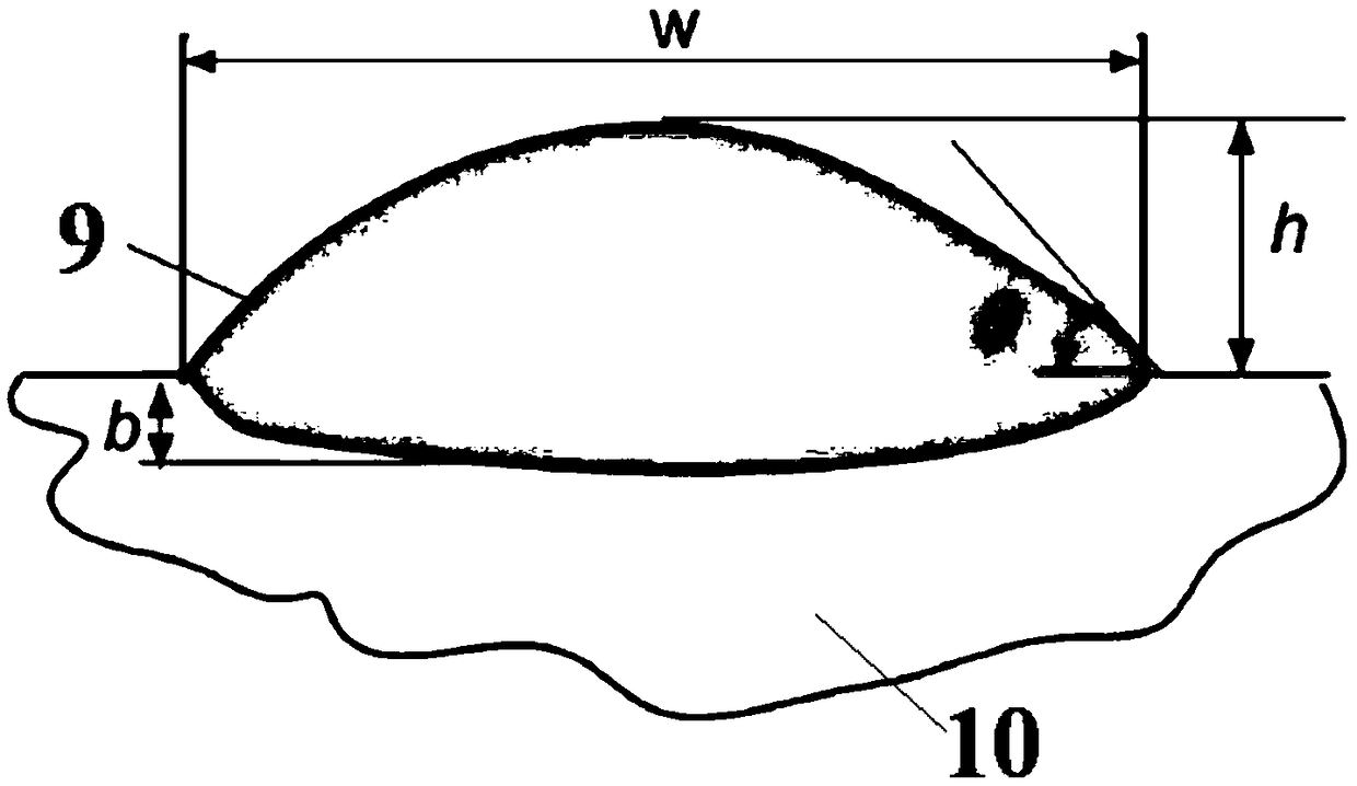
[0088] In the acquisition stage of T1 parameters, the laser scanning speed is fixed (V=10mm.s -1 ) and laser powder feeding rate (Mp=10g / min, laser spot D=4mm and laser defocus amount F=0, keep the existing parameters of the equipment unchanged during the whole processing process, the same as below), change different laser power (P = 2000 ~ 500W) for experiments, using a temperature recorder to record the temperature of the center of the molten pool and using a CCD camera to record the diameter of the molten pool to obtain the temperature center data and diameter data of the molten pool under different laser powers; determine according to the criteria Effective relationship T1, the effective interval of the molten pool diam...
Embodiment 3
[0093] The difference between this embodiment and the first embodiment is that
[0094] The powder feeding method is used for laser additive manufacturing. The powder used is Co-based alloy Stellite6, the experimental substrate is 316 stainless steel, and the strengthening phase is TiN powder.
[0095] In the acquisition stage of T1 parameters, the laser scanning speed is fixed (V=10mm.s -1 ) and laser powder feeding rate (Mp=10g / min, laser spot D=4mm and laser defocus amount F=0, keep the existing parameters of the equipment unchanged during the whole processing process, the same as below), change different laser power (P=2000~500W) to carry out the experiment, adopt the temperature recorder to record the temperature of the melting pool center and utilize the CCD camera to record the melting pool shape, obtain the melting pool temperature center data and the melting pool diameter data under different laser powers; Determine the effective relationship T1. At this time, the ef...
PUM
 Abstract
Description
Claims
Application Information