Method of rotary-connection cabin pressure removing of metering feeder and rotary-connection cabin pressure removing dynamic weighing and feeding machine

A feeder and weighing sensor technology, applied in the mechanical field, can solve problems such as spilled materials, waste of manpower and material resources, belt deviation, etc.

Pending Publication Date: 2018-11-23
刘素华
View PDF12 Cites 7 Cited by
  • Summary
  • Abstract
  • Description
  • Claims
  • Application Information

AI Technical Summary

Problems solved by technology

In large-scale large-scale production, the silo needs to be large enough to ensure the required volume. The increase in volume causes a sharp increase in the pressure of the silo. Automatic and continuous production makes the silo often full, empty, and empty. and other phenomena, the huge silo pressure and frequent changes in the silo cause a huge impact on the conveying device and weighing device, which seriously affects the stability of the conveying device and weighing device, resulting in a large weighing deviation of the weighing device. In order to correct the results, frequent adjustments are required, resulting in uncontinuous production
At present, the feeding device and weighing device use a feeder and a weighing belt conveyor under the silo, and the feeder is added to a weighing belt conveyor. There are large installation space, many equipment, high cost, and difficult adjustment and calibration. , the defect of inaccurate measurement; the current method of dynamic weighing, metering and feeding of belt feeders and A-belt feeders has a compact structure and is easy to automate, but the conveyor belts of belt feeders and A-belt feeders rely on friction The force is driven by the driving drum and the driven drum to feed the material. Because of the large amount of expansion and contraction of the belt and the nail belt, the position of the driving drum and the driven drum often needs to be adjusted to match the tension of the belt and nail belt to continue working. The distance between the rollers at both ends of the belt and the first belt is too far, which not only leads to the breakage of the belt and first belt, causing serious production stoppage accidents, but also often causes overloading of the motor power when the motor starts the belt and first belt rotation due to excessive tension, resulting in motor failure. Burnout and other shutdown failures, and because the belt is attached to the roller and rotates by friction, the two roller shafts are not parallel and the parallelograms appear at the ends of the two roller shafts when the driving roller and the driven roller are installed. In addition, the belt There are no ribs on the edge, there is a gap between the nail belt piercing strip and the perforation, and there are gaps between multiple nail plates, etc., which are affected by tension, temperature, idler rollers, and roller deflection, which will inevitably lead to belt and nail belt running. Frequent running off, resulting in leakage of material, belt, nail belt grinding guide groove, belt, nail belt running deviation, tearing and fracture, etc. Frequent maintenance and replacement on the use site has caused serious waste of manpower and material resources, reducing production efficiency and polluting the environment , the weighing unit of the belt metering feeder and weighing belt conveyor is set at the lower part of the conveyor belt, and the weighing unit weighs the materials on the conveyor belt. This structure has many factors affecting the weighing unit and is random and uncontrollable. Effective correction, resulting in the weighing accuracy can not be improved, the length of the belt type or a belt type metering feeder is short, the tension of the conveyor belt changes greatly, and a stable tension section cannot be formed, and the change of tension affects the weighing accuracy. The large error often overloads the transport plane or the transport vehicle or seriously lacks materials. After the transport vehicle is overloaded, it must find a place to unload the material, and reload the material after the lack of material, which reduces the loading and transportation efficiency and causes a lot of manpower and space. and waste of time, and also caused secondary pollution of the material to the site, air and facilities. In order to solve the above problems, the present invention proposes a method of rotating and leveling the metering feeder to remove the pressure of the warehouse and the method of removing the pressure of the warehouse by rotating and leveling. Dynamic weighing feeder
[0003] But its disadvantage is that the weighing is not accurate
With the increasing popularity of today's mining production for automation, intelligence, and remote control, the application of metering feeders in material conveying systems should be more and more extensive, but due to the weighing accuracy error of metering feeders It is far from meeting the actual needs of modern production with high efficiency, high precision, and high reliability. The main reasons for the inaccurate weighing of the weighing belt conveyor and the current metering feeder are:

Method used


Image

  • Method of rotary-connection cabin pressure removing of metering feeder and rotary-connection cabin pressure removing dynamic weighing and feeding machine
  • Method of rotary-connection cabin pressure removing of metering feeder and rotary-connection cabin pressure removing dynamic weighing and feeding machine
  • Method of rotary-connection cabin pressure removing of metering feeder and rotary-connection cabin pressure removing dynamic weighing and feeding machine

Examples


Embodiment 1

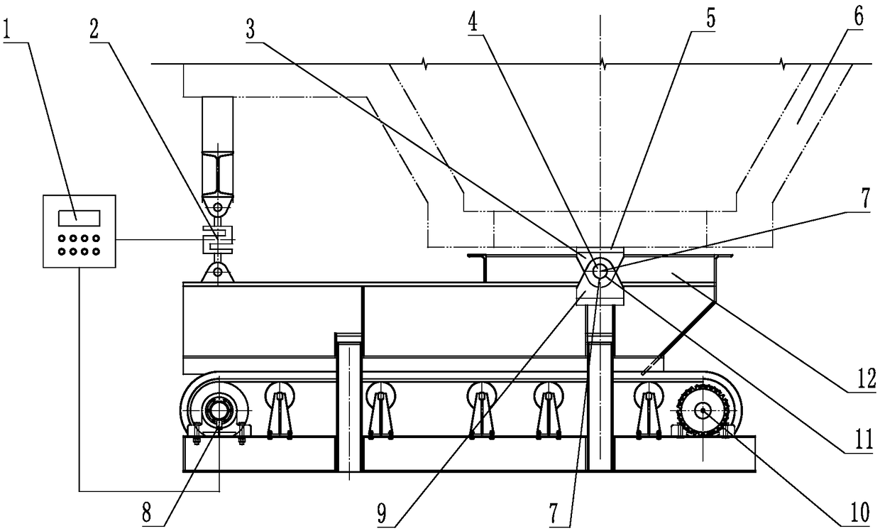
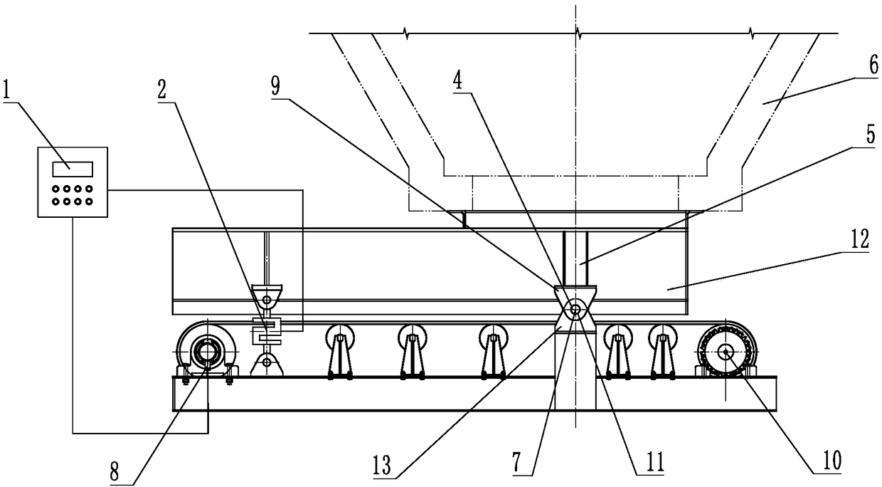
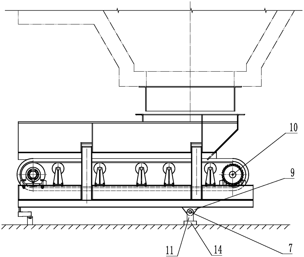
[0081] like Figure 1 to Figure 3 As shown, it is the dynamic weighing feeder for rotary-connection and flat-removal of warehouse pressure described in embodiment 1, including rotary connection hanger 5, rotary connection feeder 12, hinge shaft 4, rotary connection weighing feeder 10 , load cell 2, speed sensor 8 and computing unit 1, etc., the rotary hanger 5 and the rotary feeder 12 are separately connected or integrated, when the rotary hanger 5 and the rotary feeder 12 are split When connecting, the lower part of the rotary hanger 5 is provided with the hinged ear 3 of the hanger, the upper part of the rotary feeder 12 is provided with the rotary hinged ear 9 of the hopper, and the bottom of the rotary feeder 12 is provided with a rotary weigher. Conveyor 10, etc., the rotating hanger 5 is hung on the silo mouth 23 or set on the support foundation 14, and the axis of the hanger is screwed and hinged ear hole 11 is set at the middle point of the pressure affected area of ​​...

Embodiment 2

[0085] like Figure 4 to Figure 8 As shown, it is the dynamic weighing feeder for rotary connection and flat removal of warehouse pressure described in embodiment 2. The rotary connection weighing feeder 10 includes a drum 16, a conveyor belt 15 and a driving device 18, etc., and the speed sensor 8 is arranged on The roller 16 or the speed sensor 8 is set on the conveyor belt 15 or the speed sensor 8 is set on the driving device 18, and the receiving end 17 of the rotary feeder is directly connected with the silo port 23 or the upper part of the rotary feeder 12 is provided with a feeding chute 20. The feeding chute 20 of the rotary feeder 12 is provided with a control gate 19, the feeding chute 20 is connected separately or integrally with the rotary feeder 12, and the weighing sensor 2 is connected with the rotary weighing feeder 10 directly connected or provided with a shock absorber 21, or a shock absorber 21 is provided between the hinged ear 3 and the hinge shaft 4 of th...

Embodiment 3

[0088] like Figure 9 As shown, it is the dynamic weighing feeder described in the embodiment 3, the screw-connected hanger 5 or the screw-connected feeder 12 is provided with a material flow shaper 24 at the butt joint of the screw-connected feeder 12 and the bin mouth 23. , the material flow shaper 24 arranges the shape, flow direction, and flow rate of the material flowing into the rotary weighing conveyor 10, so that the pressure center point of the pressure zone of the material bin 6 is relatively stable, and the support hinge point 7 of the feeder is kept in the bin for a long time. The central point of the bin pressure in the nip area ensures that the bin pressure forces on both sides of the feeder support hinge point 7 are equal in magnitude and balanced with each other during the material flow process.

[0089] All the other are with embodiment 1.


PUM


Abstract

The invention belongs to the field of machinery, and particularly relates to a method of rotary-connection cabin pressure removing of a metering feeder and a rotary-connection cabin pressure removingdynamic weighing and feeding machine. The weighing and feeding machine comprises a rotary-connection hanging frame, a rotary-connecting material receiving device, a hinge shaft, a rotary-connection weighing and material conveying device, a weighing sensor, a speed sensor and an arithmetic unit, wherein the weighing sensor is arranged at the end part, far away from a feeding machine supporting hinge point, of the rotary-connection weighing and material conveying device, the weighing sensor senses the change of the applied force of the rotary-connection weighing and material conveying device, the weighing sensor cooperates with the speed sensor to calculate the weight of a material conveyed by the rotary-connection weighing and material conveying device through the arithmetic unit. Accordingto the method and the machine, manpower and material resources are saved, a dirty, disorder, bad and abominable labor scene is changed into an environment which is clean, order, free of leaking material, and free of dust, so that the long-term stability and reliability of the weighing are ensured, and the working efficiency and the working quality are improved.

Description

technical field [0001] The invention belongs to the field of machinery, and in particular relates to a method for rotating and leveling a metering feeder to remove pressure from bins and a dynamic weighing feeder for rotating and leveling to remove bin pressure. Background technique [0002] At present, the field of material storage and transportation is developing rapidly in the direction of automation, intelligence, and remoteness. The material storage and transportation system generally includes three parts: silos, conveying devices and weighing devices. In large-scale large-scale production, the silo needs to be large enough to ensure the required volume. The increase in volume causes a sharp increase in the pressure of the silo. Automatic and continuous production makes the silo often full, empty, and empty. and other phenomena, the huge silo pressure and frequent changes in the silo cause a huge impact on the conveying device and weighing device, which seriously affect...

Claims


Application Information

Patent Timeline
IPC IPC(8): B65G65/42B65G47/74B65G43/00B65D88/54B65D90/22B65D90/00
CPCB65G15/32B65G17/02B65G17/42B65G23/06B65G41/006B65G43/08B65G45/08B65G47/18B65G47/42B65G69/0441B65G2207/20B65G2203/0258B65D88/54B65D90/00B65D90/22B65G17/06B65G21/20B65G41/00B65G43/00B65G47/74B65G65/42B65G69/04F16H9/24G01G11/00
Inventor 刘素华
Owner 刘素华
Why Eureka
Try Eureka