
Electrolytic bath for copper displacement by iron

A technology of electrolytic cell and cell body, applied in electrolytic process, electrolytic components, electrodes, etc., can solve the problems of uneconomical large-scale application, secondary pollution of anode chlorine gas, and low added value of products, and achieve low-cost large-scale application, High electrolysis current efficiency, avoiding excessive consumption

Inactive Publication Date: 2018-11-23
苏碧云
View PDF4 Cites 6 Cited by
  • Summary
  • Abstract
  • Description
  • Claims
  • Application Information

AI Technical Summary

Problems solved by technology

However, this method requires the iron added to the waste liquid to be reduced iron powder or iron flakes with a large specific surface area, and the replacement reaction occurs directly on the surface of the iron, the reaction rate is slow and the sponge copper is produced to wrap on the iron surface, resulting in iron The consumption is large, the purity of copper products is only about 70%, and the added value of the products is not high
Some existing technologies also use ion membrane isolation electrolysis, but this method has a small scale of treatment, and the anode is prone to generate chlorine gas to cause secondary pollution, and the cost of ion membrane is expensive, so it is not economical for large-scale application

Method used


Image

  • Electrolytic bath for copper displacement by iron
  • Electrolytic bath for copper displacement by iron

Examples


Embodiment Construction

[0020] The following will clearly and completely describe the technical solutions in the embodiments of the present invention with reference to the accompanying drawings of the present invention. The embodiments described below are only part of the embodiments of the present invention based on the solutions disclosed in the present invention, and all other embodiments obtained by those of ordinary skill in the art without creative efforts fall within the protection scope of the present invention.

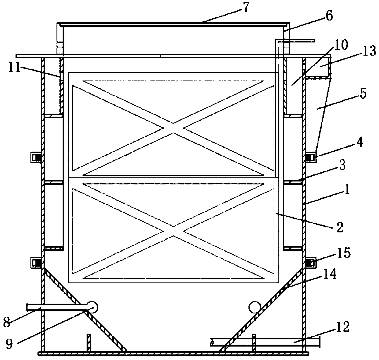
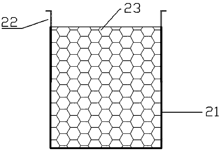
[0021] combine figure 2 Anodized titanium frame structure, such as figure 1 As shown, there is an electrode 2 inside the main tank body 1, and the electrode 2 includes a grid-shaped anode titanium frame and a cathode copper / titanium sheet; the internal support rib 3 is located on the inner wall of the main tank body 1, and the top external reinforcement hoop 4 and the bottom side external reinforcement hoop 15 are located on the outer wall of the main tank body 1; the exhaust gas ...


PUM


Abstract

The invention discloses an electrolytic bath for copper displacement by iron. The electrolytic bath for copper displacement by iron is used for extracting metal copper from acid etching waste liquid.An anode titanium frame and a cathode copper / titanium sheet are alternately put inside the electrolytic bath; waste iron is put in the anode titanium frame; the anode titanium frame is connected witha direct current power supply positive electrode; the cathode copper / titanium sheet is connected with a direct current power supply negative electrode; the acid etching waste liquid is pumped from a bottom feeding pipe of the electrolytic bath for copper displacement by iron; under the effect of a direct current electric field, the anode titanium frame iron sheet is dissolved; the copper is separated out at the anode copper sheet / titanium sheet. The acid etching waste liquid after the electrolysis flows back to an external liquid inlet device through a built-in overflow groove for cyclic collection and then flows back into the electrolytic bath. When the concentration of the copper ion in the acid etching waste liquid is reduced to a certain concentration, the waste liquid is pumped intoan external storage device through a bottom discharge pipe of the electrolytic bath for copper displacement by iron, and is then pumped into the external electrolytic bath from the external storage device for byproduct recovery through electrolysis. The electrolytic bath for copper displacement by iron belongs to the electrolytic bath specially used for recovering copper in the acid etching wasteliquid through a process of inducting copper displacement by iron via the external electric field. The copper in the acid etching waste liquid can be effectively recovered.

Description

technical field [0001] The invention relates to the field of recovering non-ferrous metals from waste liquids, in particular to a device for recovering metal copper from acidic etching waste liquids by electrolysis. Background technique [0002] A large amount of acid etching solution is consumed during the etching process of printed circuit board (PCB), and the concentration of monovalent copper ions in the resulting acid etching waste solution is high. Most circuit board companies that produce high-precision multilayer circuit boards will choose to use Etching waste liquid is sold to companies that specialize in waste liquid treatment. Therefore, these recycling companies have a huge amount of acidic etching waste liquid to be treated. [0003] In the existing technology, the method for recovering metal copper from acidic etching waste liquid is mainly the process of replacing copper with iron. The principle of the iron-replacement-copper process is to use iron, which is...

Claims


Application Information

Patent Timeline
IPC IPC(8): C25C1/12C25C7/00C25C7/06C25C7/02C23F1/46
CPCC23F1/46C25C1/12C25C7/00C25C7/02C25C7/06Y02P10/20
Inventor 武斌苏碧云
Owner 苏碧云
Learn More