Eureka AIR delivers breakthrough ideas for toughest innovation challenges, trusted by R&D personnel around the world.

Denitration system and method for cooperative high-temperature ammonia spraying of low-nitrogen combustor of utility boiler

A low-nitrogen burner and power plant boiler technology, which is applied to chemical instruments and methods, separation methods, and dispersed particle separation, can solve problems such as low denitrification efficiency, increased operating costs, and high NOx emissions, so as to promote denitrification reactions and reduce The effect of small oxygen content

Active Publication Date: 2018-11-30
CHINA HUANENG GRP CO LTD +1
View PDF16 Cites 7 Cited by
  • Summary
  • Abstract
  • Description
  • Claims
  • Application Information

AI Technical Summary

Problems solved by technology

Invention patents "Porous Ammonia Injection Device for High Temperature Reduction Zone of W Flame Boiler" (Patent No. CN201710818917.6) and "Swirl Burner W Flame Boiler with Inner Direct Outer Rotary Ammonia Injection Device" (Patent No. CN201710818425.7 ) proposes to arrange ammonia injection device in the high temperature reduction area of ​​W flame boiler to solve the problems of high NOx emission and low denitrification efficiency of W flame boiler
Flue gas recirculation technology can create a reducing atmosphere in the main combustion zone, and at the same time improve the efficiency of fly ash burnout, but when the amount of recirculated flue gas is large, the operating cost increases and the unit economy decreases

Method used


Image

  • Denitration system and method for cooperative high-temperature ammonia spraying of low-nitrogen combustor of utility boiler

Examples


Embodiment Construction

[0031] The present invention will be further described in detail below in conjunction with specific embodiments, which are explanations of the present invention rather than limitations.

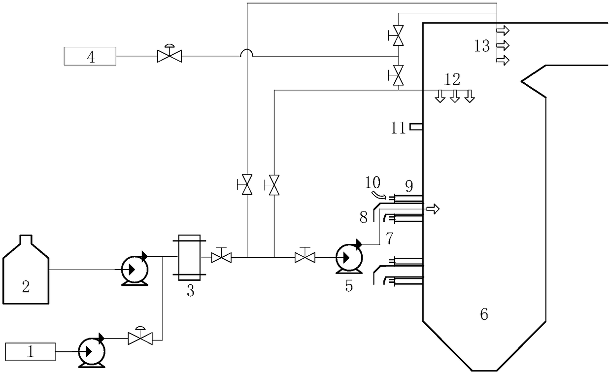
[0032] The present invention is a denitrification system in which the low-nitrogen burner of a power station boiler cooperates with high-temperature ammonia injection, such as figure 1 As shown, it includes a urea solution supply system, a set of burners set on the utility boiler 6, an OFA nozzle 11 connected to the SOFA air, a wall spray gun 12 and a long spray gun 13; the secondary burner of the uppermost burner of the burner set The air pipe 9 is connected to the recirculation flue gas pipeline 10, and the primary air pipeline 8 is provided with an ammonia spray gun 7; the secondary air pipeline of other burners is connected to the air; the ammonia spray gun 7, the wall spray gun 12 and the long spray gun 13 are respectively The urea solution is provided by the connected urea solution supp...


PUM


Abstract

The invention provides a denitration system and method for cooperative high-temperature ammonia spraying of a low-nitrogen combustor of a utility boiler. The system comprises a urea solution supply system, a combustor group arranged on a utility boiler, an OFA spraying opening for introducing SOFA air, wall type spray guns and long spray guns; a secondary air pipe of the uppermost-layer combustorof the combustor groups is connected with a recirculating flue gas pipeline and an ammonia spray gun is arranged in a primary air pipeline; air is introduced into secondary air pipelines of other combustors; and the ammonia spray guns, the wall type spray guns and the long spray guns are respectively used to provide a urea solution through a connected urea solution supply system. The reducing agent coverage range is improved. The retention time of ammonia gas in a reducing atmosphere is remarkably prolonged, and the denitration efficiency can be improved. Escaped ammonia is oxidized in an SOFAair region, and the ammonia escaping level can be reduced. Water in the urea solution reacts with coke to generate OH active radicals, so that the reduction performance of flue gas in a combustor region can be improved, reactions of the ammonia gas with nitrogen oxides are promoted, and denitration efficiency is improved.

Description

technical field [0001] The invention relates to flue gas denitrification technology in thermal power plants, in particular to a denitrification system and method in which low-nitrogen burners of power plant boilers cooperate with high-temperature ammonia injection. Background technique [0002] Pulverized coal combustion is the main combustion method for power production in my country. At present, the NOx emission level of power plant boiler pulverized coal (medium-to-high volatile) combustion is about 150mg / m 3 up to 300mg / m 3 between. In order to realize the NOx emission of coal-fired units is less than 50mg / m 3 , research and development of joint denitrification, multi-stage or multi-stage composite denitrification process will be an important development direction of denitrification technology. [0003] Selective non-catalytic reduction (SNCR) is the mainstream technology for flue gas denitration in power plant boilers, fluidized bed boilers, cement kilns and waste in...

Claims


Application Information

Patent Timeline
IPC IPC(8): B01D53/79B01D53/78B01D53/56
CPCB01D53/56B01D53/78B01D53/79B01D2251/2067
Inventor 张向宇陆续张波高宁向小凤徐宏杰
Owner CHINA HUANENG GRP CO LTD
Why Eureka
Eureka Blog
Learn More