Thermal optical property representation and optimization method of optical window under low-temperature vacuum environment

An optical window and low-temperature vacuum technology, applied in the field of optical thermal analysis, can solve the problems of difficult operation, high cost, and insufficient characterization, and achieve the effect of difficult operation, convenient operation and simple structure

Active Publication Date: 2018-11-30
NANJING UNIV OF SCI & TECH
View PDF3 Cites 4 Cited by
  • Summary
  • Abstract
  • Description
  • Claims
  • Application Information

AI Technical Summary

Problems solved by technology

[0004] At present, the thermo-optical simulation of the optical window mainly includes: first, use the temperature analysis function of the optical design software for analysis, its limitation is that it can only analyze the axial temperature field, and cannot accurately simulate the real environment where the window is located; It uses finite element software such as ANSYS to analyze the influence of temperature and pressure on the surface shape, and fits the node deformation into a Zernike polynomial representation, and transfers it to the optical design software for analysis, without considering the influence of refractive index changes on optical performance; the third is Use the formula of refractive index change with temperature to solve the refractive index of each point, use the gradient refractive index formula to fit, and transfer the fitted data to the optical design software for analysis. This method does not consider the influence of its surface shape change
Literature "Design of an off-axis parabolic mirror aberration correction lens group, Acta Optics Sinica, 2014, 34(6): 219-224." and patent "Large field of view off-axis main focus type collimator optical system CN 20333792

Method used


Image

  • Thermal optical property representation and optimization method of optical window under low-temperature vacuum environment
  • Thermal optical property representation and optimization method of optical window under low-temperature vacuum environment
  • Thermal optical property representation and optimization method of optical window under low-temperature vacuum environment

Examples


Embodiment 1

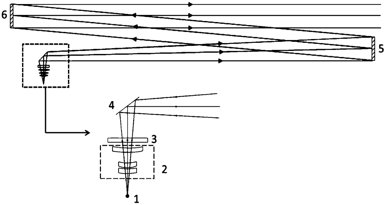
[0062] A thermo-optical characteristic characterization and optimization method of an optical window in a low-temperature vacuum environment, the method steps are as follows:

[0063] Step 1, establish the optical design model of the large-aperture collimator (in ZEMAX software), and form the large-aperture collimator system;

[0064] combine figure 1 , to establish the initial structure, which only contains the optical window 3, the first plane mirror 4, the second plane mirror 5 and the off-axis paraboloid 6, such as Figure 4 As shown in (a1) and (a2), the wave aberration in most of the field of view of the system is above the diffraction limit.

[0065] Step 2, using an afocal offset lens group to optimize the off-axis field of view aberration of the large aperture collimator system;

[0066] In the optical design software ZEMAX, the light path of the large-aperture collimator is established. The light source 1 emits a bunch of spherical waves that enter the offset lens ...


PUM


Abstract

The invention discloses a thermal optical property representation and optimization method of an optical window under a low-temperature vacuum environment, wherein a fused quartz window in a large-diameter parallel optical tube system under the low-temperature vacuum environment is simulated through a finite element method. The method is based on a customized surface type of an optical design software, wherein the surface type is combined with an even order aspheric surface type and the surface type of a gradient refractive index surface and used for representing optical window surface shape variation and material refractive index variation caused by temperature difference and pressure difference. A biasing afocal lens group is used for optimizing off-axis field of view wave aberration of the large-diameter parallel optical tube system, after surface shape variation caused by temperature variation is added, a zoom design is used for compensating system wave aberration and focal length variation caused by temperature, the wave aberration is optimized to be less than diffraction limit, thus, requirements of use are satisfied. The method has the advantages of comprehensively representing the optical window thermal optical property, using a small-diameter element for optimizing aberration of the large-diameter element, being adaptive to various temperature variations, being simple in structure, and so on.

Description

technical field [0001] The invention belongs to the field of optical thermal analysis, and in particular relates to a method for characterization and optimization of thermo-optical characteristics of an optical window in a low-temperature vacuum environment. Background technique [0002] As a common optical element, the optical window is widely used as an optical channel of the optical system in space payloads and equipment such as submarines, tanks, and missiles. It plays the role of light transmission, pressure isolation, and temperature isolation. Its optical performance directly affects The performance of the optical system. [0003] When the optical window is in use, the two sides are usually in different environments. The resulting temperature and pressure differences will change the surface shape of the optical window and the refractive index of the material, thereby changing the transmitted wavefront of the optical window and affecting the imaging quality of the subs...

Claims


Application Information

Patent Timeline
IPC IPC(8): G02B27/00
CPCG02B27/0012
Inventor 高志山倪瑞沪袁群姚艳霞王若言陈铭
Owner NANJING UNIV OF SCI & TECH
Why Eureka
Try Eureka