a vacuum glass

A vacuum glass and glass technology, which is applied in the field of glass deep processing, can solve the problems of reducing the strength of the bottom glass, time-consuming and laborious processing, and shortening the service life, and achieves the effects of improving the compressive strength, low process cost, and improving the thermal insulation effect.

Active Publication Date: 2021-06-04
张跃
View PDF7 Cites 0 Cited by
  • Summary
  • Abstract
  • Description
  • Claims
  • Application Information

AI Technical Summary

Problems solved by technology

However, because the vacuum space of this invention is very small, only a few tenths of a millimeter, if there is a slight leak, the vacuum will be lost immediately, which will greatly reduce the service life. The gas leaking into the middle layer ensures the long life of the vacuum glass, but the groove on the upper surface of the lower glass to accommodate the getter will make the structure complicated, the processing is time-consuming and laborious, and the existence of the groove will reduce the The strength of the lower glass

Method used


Image

  • a vacuum glass
  • a vacuum glass
  • a vacuum glass

Examples


Embodiment 1

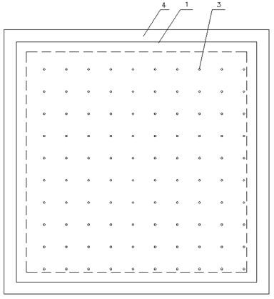
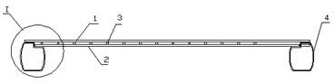
[0034] Such as Figure 1~Figure 3 Shown: a vacuum glass, including a first glass 1, a second glass 2 and a support 3 between the two layers of glass, the first glass 1 and the second glass 2 are surrounded by a frame 4, and the two layers of glass A vacuum cavity 5 is formed between them; the frame 4 , the support member 3 and the first glass 1 and the second glass 2 are connected by a sealant 6 .

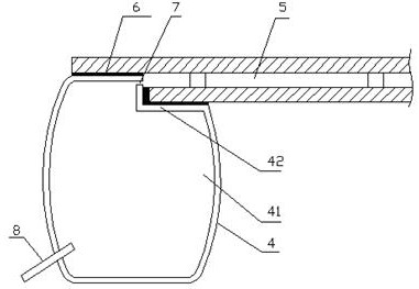
[0035] Specifically, the frame 4 is provided with an inner cavity 41, and the inner cavity 41 of the frame 4 communicates with the vacuum chamber 5, so that a large vacuum space is formed between the two layers of glass. Both ends of the frame 4 are connected with the vacuum glass through a sealant 6 . One end of the frame 4 is provided with a step 42, and the second glass 2 is embedded in the step, and the sealant 6 is applied between the step 42 and the second glass 2. Compared with applying an adhesive layer on a horizontal plane, the bonding strength and airtightness are bette...

Embodiment 2

[0048] Such as Figure 4 Shown: the difference with embodiment 1 is that the two ends of frame 4 ' are connected with vacuum glass by sealant 6. One end of the frame 4' is provided with a step 42', the second glass 2 is embedded in the step, and a sealant 6 is applied between the step 42' and the second glass 2, and the upper end of the step 42' is higher than a part of the upper surface of the second glass; The other end of the frame 4' is parallel to the side end of the first glass, and is higher than a part of the lower surface of the first glass, and a sealant 6 is applied between the other end of the frame 4' and the side end of the first glass 1, and the sealant 6 also covers the corners of the first glass.

[0049] Others are the same as embodiment 1.

Embodiment 3

[0051] Such as Figure 5 Shown: The difference from Example 1 is that the distance between the first glass 1 and the second glass 2 is 0.2mm, and the height of the inner cavity of the frame 4" is 100 times the distance between the first glass 1 and the second glass 2.

[0052] The support member 3" is made of stainless steel and has a hollow structure.

[0053] The space between the exhaust pipe 8 and the frame 4" is also sealed by a sealant.

[0054] The two ends of the frame 4" are connected with the vacuum glass through the sealant 6. One end of the frame 4" is provided with a step 42", the second glass 2 is embedded in the step, and the sealant 6 is applied between the step 42" and the second glass 2 The upper end of the step 42" is lower than the upper surface of the second glass 2; the other end of the frame 4" is parallel to the horizontal plane of the first glass 1, and a sealant 6 is applied between the lower surface of the first glass 1.

[0055] Others are the sam...


PUM


Abstract

A vacuum glass, comprising a first glass, a second glass and a plurality of support members arranged between two layers of glass, a vacuum chamber is formed between the two layers of glass; the surroundings of the first glass and the second glass are sealed by a frame; the The frame is provided with an inner cavity, and the inner cavity of the frame communicates with the vacuum cavity, so that a large vacuum space is formed between the two layers of glass. On the one hand, the invention has simple manufacturing process and control process, low process cost, and greatly reduces the vacuum leakage rate; on the other hand, it can ensure the original strength and flatness of the glass without thermal deformation, thereby obtaining a long-life, high-quality vacuum Glass.

Description

technical field [0001] The invention relates to the field of glass deep processing, in particular to vacuum glass. Background technique [0002] Vacuum glass is to seal the surroundings of two pieces of flat glass, vacuumize the gap and seal the exhaust hole. The gap between the two pieces of glass is 0.1-0.2mm. Generally, at least one of the two pieces of vacuum glass is low-emissivity glass. , so that the heat loss through the conduction, convection and radiation of the vacuum glass is minimized. [0003] CN 204897748U discloses a vacuum glass, comprising upper glass, lower glass and getter, the upper glass and the lower glass are separated by supports, and a vacuum layer is formed between the upper glass and the lower glass , a groove for accommodating the getter is provided on the upper surface of the lower glass, and a through hole penetrating along the thickness of the lower glass is arranged on the bottom surface of the groove, and the through hole is used as an exha...

Claims


Application Information

Patent Timeline
Patent Type & Authority Patents(China)
IPC IPC(8): C03C27/12
CPCC03C27/10
Inventor 张跃
Owner 张跃
Why Eureka
Try Eureka