Switch cabinet condensation prevention intelligent detection and control system

A technology of intelligent detection and control system, applied in the direction of substation/distribution device casing, etc., can solve the problem of accelerated aging of equipment in the cabinet, and achieve the effects of excellent mechanical performance and insulation performance, simple synthesis, and enhanced stability.

Pending Publication Date: 2018-12-07
NANYANG POWER SUPPLY COMPANY OF STATE GRID HENAN ELECTRIC POWER
View PDF14 Cites 4 Cited by
  • Summary
  • Abstract
  • Description
  • Claims
  • Application Information

AI Technical Summary

Problems solved by technology

And if the temperature in the cabinet is too high for a long ...

Method used


Image

  • Switch cabinet condensation prevention intelligent detection and control system
  • Switch cabinet condensation prevention intelligent detection and control system
  • Switch cabinet condensation prevention intelligent detection and control system

Examples


Embodiment 1

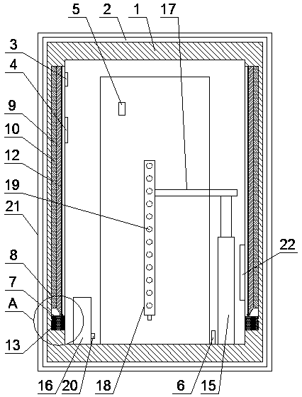
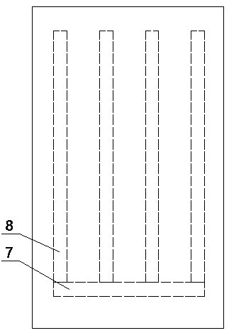
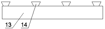
[0037] Such as figure 1 , figure 2 , image 3 with Figure 4 As shown, a switch cabinet anti-condensation intelligent detection and control system includes a cabinet body 1, the outer surface of the cabinet body 1 is provided with an insulation layer 2, and the inner wall of the cabinet body 1 is provided with a condensation generating mechanism. A first temperature sensor 3 is arranged on the inner wall of the body 1, a dew point meter 4 for detecting the dew point temperature of the internal air is arranged in the cabinet body 1, a second temperature sensor 5 is arranged on the outer surface of the electrical equipment in the cabinet body 1, and the A drying mechanism for drying electrical equipment is arranged in the cabinet body 1, and a PLC controller 6 is arranged in the cabinet body 1, and the PLC controller 6 is connected with the first temperature sensor 3, the dew point meter 4, and the second temperature sensor. The sensor 5, the condensation generating mechanis...

Embodiment 2

[0051] The difference from Example 1 is that the waterproof layer 21 contains components and their contents: 16 parts by weight of polyaniline, 2.5 parts by weight of polymethyl methacrylate, 7 parts by weight of chloroform, N,N- 42 parts by weight of dimethylformamide, 16 parts by weight of sodium silicate, 2.8 parts by weight of sodium lauryl sulfate, 8 parts by weight of nano silicon dioxide, 6 parts by weight of sodium methyl silicate, tetrachloroterephthalic acid 3.7 parts by weight of dimethyl ester, 8.9 parts by weight of cinnamaldehyde, 23 parts by weight of acetone, and 48 parts by weight of deionized water.

Embodiment 3

[0053] The difference from Example 1 is that the waterproof layer 21 contains components and their contents: 17 parts by weight of polyaniline, 3 parts by weight of polymethyl methacrylate, 7.5 parts by weight of chloroform, N,N- 44 parts by weight of dimethylformamide, 16.5 parts by weight of sodium silicate, 3 parts by weight of sodium lauryl sulfate, 9 parts by weight of nano silicon dioxide, 6.1 parts by weight of calcium stearate, tetrachloroterephthalic acid di 3.9 parts by weight of methyl ester, 9 parts by weight of polyaspartic acid, 24 parts by weight of acetone, and 50 parts by weight of deionized water.


PUM

PropertyMeasurementUnit
Thicknessaaaaaaaaaa
Thicknessaaaaaaaaaa
Tensile strengthaaaaaaaaaa

Abstract

The invention discloses a switch cabinet condensation prevention intelligent detection and control system comprising a cabinet body. The outer surface of the cabinet body is provided with a heat preservation layer. The inner wall of the cabinet body is provided with a condensation generation mechanism. The inner wall of the cabinet body is provided with a first temperature sensor. The cabinet bodyis internally provided with a dew point instrument which is used for detecting the inner air dew point temperature. The outer surface of the electrical equipment in the cabinet body is provided witha second temperature sensor. The cabinet body is internally provided with a drying mechanism which is used for drying the electrical equipment. The cabinet body is internally provided with a PLC. Thecold iron bars of which the temperature is lower than that of the surface of the electrical equipment in the switch cabinet can be provided and the condensation phenomenon is enabled to occur on the surface of the cold iron bars by priority and the condensed drops of water drops into the container filled with the desiccant along the cold iron bars so that the probability of condensation on the electrical equipment in the switch cabinet can be greatly reduced; besides, the electrical equipment can be dried by using the drying mechanism in the cabinet body so as to further avoid the condensationphenomenon on the electrical equipment.

Description

technical field [0001] The invention relates to the field of anti-condensation technology for lighting cabinets, in particular to an intelligent detection and control system for anti-condensation of switch cabinets. Background technique [0002] The switchgear is a very important electrical equipment in the power system. In the power system, the switchgear is responsible for the dual functions of closing and disconnecting the power line and protecting the safety of the system. With the rapid development of electric power towards high voltage, large units, and large capacity, the growing power grid and the popularization and promotion of substation unattended management mode and comprehensive automation, the safe operation of switchgear is becoming more and more important, and the modern power system has a great impact on power quality. The requirements are getting higher and higher, and correspondingly higher requirements are put forward for the reliability of the switchgear...

Claims


Application Information

Patent Timeline
IPC IPC(8): H02B1/28C08L79/02C08L33/12C08K13/02C08K3/36C08K5/098
CPCH02B1/28C08L79/02C08L33/12C08K13/02C08K3/36C08K5/098C08K3/34
Inventor 王雷罗道军姚楠
Owner NANYANG POWER SUPPLY COMPANY OF STATE GRID HENAN ELECTRIC POWER
Why Eureka
Try Eureka