A hybrid system for excavators

A hybrid power system and hybrid technology, applied to earth movers/shovels, construction, etc., can solve problems such as the impact of boom falling speed, inconvenient installation of accumulators, pressure rise, etc., and achieve significant energy saving effects , Improve energy utilization efficiency and reduce installed power

Active Publication Date: 2021-08-13
XUZHOU COLLEGE OF INDAL TECH
View PDF4 Cites 0 Cited by
  • Summary
  • Abstract
  • Description
  • Claims
  • Application Information

AI Technical Summary

Problems solved by technology

The hydraulic recovery scheme takes advantage of the accumulator’s high power density and the ability to absorb pressure shocks. However, due to the low density of energy stored in the accumulator, if more energy needs to be stored, a larger accumulator will be required, which in turn will Occupies a large space, and the installation of the accumulator is also very inconvenient
In addition, the pressure of the accumulator will rise with the increase of the stored oil, which will affect the falling speed of the boom

Method used


Image

  • A hybrid system for excavators
  • A hybrid system for excavators
  • A hybrid system for excavators

Examples


Embodiment 1

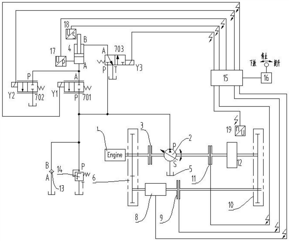
[0037] Such as figure 2 As shown, a series hybrid system for an excavator includes a prime mover 1, a hydraulic pump / motor 2, a boom hydraulic cylinder 4, a second reversing valve 702, a speed sensor 19, a pressure sensor 17, a flywheel 12 and a controller 15, the prime mover 1 is connected with the hydraulic pump / motor 2 through the transfer case 6, the prime mover 1 is generally an engine such as a diesel engine, and may also be an electric motor. The oil suction port S of the hydraulic pump / motor 2 is connected to the oil tank 5;

[0038] A third clutch 3 is connected in series between the transfer case 6 and the hydraulic pump / motor 2;

[0039] The oil outlet P of the hydraulic pump / motor 2 is respectively connected with the P port of the first reversing valve 701 and the P port of the third reversing valve 703; Port A is respectively connected to the rodless cavity and the rod cavity of the boom hydraulic cylinder 4; the T port of the third reversing valve 703 is conne...

Embodiment 2

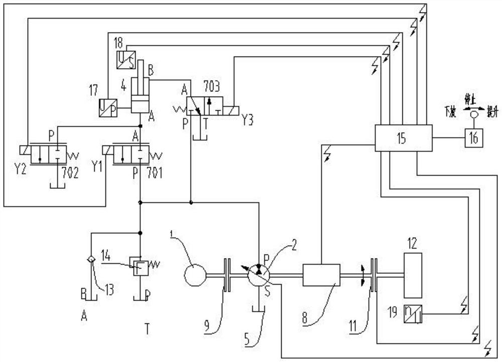
[0061] Such as image 3 As shown, a series hybrid system for excavators includes prime mover 1, hydraulic pump / motor 2, boom hydraulic cylinder 4, second reversing valve 702, speed sensor 19, pressure sensor 17 and control Device 15; the prime mover 1 is connected with the hydraulic pump / motor 2 in transmission, and the prime mover 1 is generally an engine such as a diesel engine, and may also be an electric motor. The oil suction port S of the hydraulic pump / motor 2 is connected to the oil tank 5;

[0062] The prime mover 1 is connected to the hydraulic pump / motor 2 through the first clutch 9 . For the clutch, when the power is on, the clutch is engaged; when the power is off, the clutch is disengaged.

[0063] The oil outlet P of the hydraulic pump / motor 2 is respectively connected with the P port of the first reversing valve 701 and the P port of the third reversing valve 703; Port A is respectively connected to the rodless cavity and the rod cavity of the boom hydraulic...


PUM


Abstract

A series hybrid power system for excavators, the oil outlet P of the hydraulic pump / motor is respectively connected to the P port of the first reversing valve and the P port of the third reversing valve; the first and third reversing valves The A port of the directional valve is respectively connected with the rodless cavity and the rod cavity of the boom hydraulic cylinder; the T port of the third directional valve is connected with the oil tank; the P port and T port of the second directional valve are connected with the first directional control valve respectively. Port A of the valve is connected to the oil tank; the prime mover is connected to the hydraulic pump / motor through the transfer case, and the other power output port of the transfer case is connected to a continuously variable transmission, which is connected to a power port of the gearbox through the first clutch connection; one end of the flywheel is connected to the hydraulic pump / motor through the second clutch, and the other end of the flywheel is connected to the other power port of the gearbox; the speed sensor is set on the flywheel housing; the pressure sensor is set on the boom hydraulic cylinder Stemless cavity. The system can realize the recovery and reuse of the power of the prime mover, and can improve the energy utilization efficiency of the system.

Description

technical field [0001] The invention belongs to the technical field of hydraulic transmission, and in particular relates to a series hybrid power system for excavators. Background technique [0002] Hydraulic excavators are widely used in various construction fields. Hydraulic excavators have disadvantages such as high fuel consumption and low efficiency. Research on energy saving is imminent. [0003] During the working process of the excavator, there are often times when the output power of the prime mover is greater than the system demand. This will cause a certain waste of power, causing the prime mover to work in an inefficient area. During the working process of the excavator, the boom lifts frequently, and due to the large mass of the working device and the load, a large amount of potential energy will be released during the descent. Most of the energy is consumed at the throttle port of the main hydraulic valve and converted into heat energy, which causes waste of ...

Claims


Application Information

Patent Timeline
Patent Type & Authority Patents(China)
IPC IPC(8): E02F9/22
CPCE02F9/2264E02F9/2267
Inventor 李建松孙金海周波黎少辉张文婷
Owner XUZHOU COLLEGE OF INDAL TECH
Why Eureka
Try Eureka