Exhaust pipe heat insulation shield and installation method

A technology for thermal insulation and heat insulation, which is applied to exhaust devices, mufflers, engine components, etc., can solve problems such as unsatisfactory thermal insulation effect, easy scratches on the surface of the heat insulation cover, and unsightly overall appearance. , to achieve the effect of ensuring thermal insulation effect, saving process steps and simple structure

Pending Publication Date: 2018-12-11
苏州普科环境技术有限公司
View PDF2 Cites 4 Cited by
  • Summary
  • Abstract
  • Description
  • Claims
  • Application Information

AI Technical Summary

Problems solved by technology

At present, the traditional heat insulation cover usually adopts double-layer aluminum foil or multi-layer cloth structure, the structure is complex and the heat insulation effect is not ideal, and the surface of the heat insulation cover is easily scratched, the strength is insufficient, and the overall appearance is not beautiful

Method used


Image

  • Exhaust pipe heat insulation shield and installation method
  • Exhaust pipe heat insulation shield and installation method
  • Exhaust pipe heat insulation shield and installation method

Examples


Embodiment 1

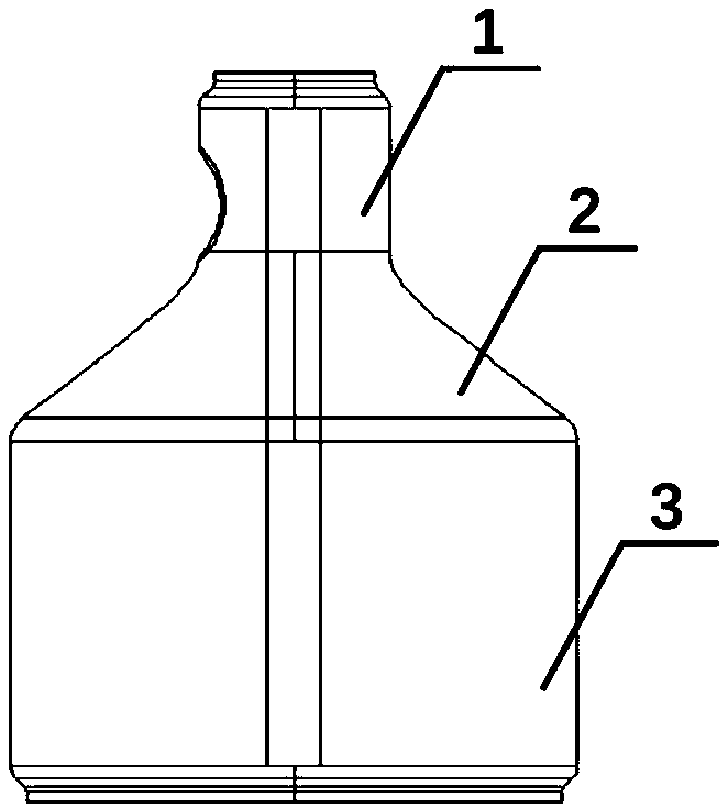
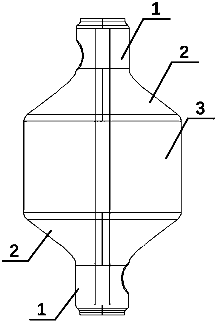
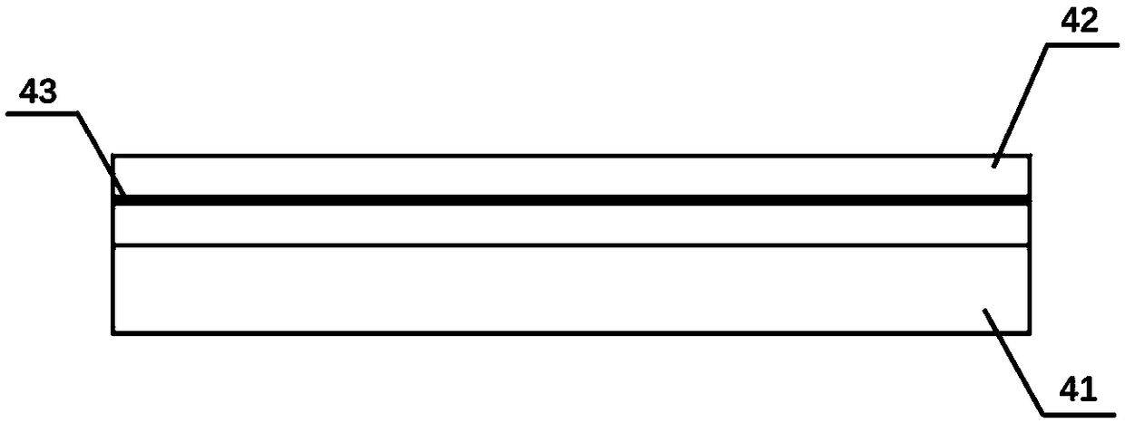
[0040] Such as figure 1 , 3 The present invention discloses a thermal insulation cover for an exhaust pipe, which includes a first heat shield 1 , a second heat shield 2 and a third heat shield 3 . The first heat shield 1 , the second heat shield 2 , and the third heat shield 3 are all composed of a metal shell 41 and a thermal insulation layer 42 . The thermal insulation layer 42 is bonded and fixed on the surface of the metal shell 41, which can ensure the bonding force between the thermal insulation layer 42 and the metal shell 41, and prevent the thermal insulation layer 42 from falling off during use, which affects the thermal insulation effect. The thermal insulation cover is wrapped on the outside of the exhaust pipe during use, and the thermal insulation layer 42 is in contact with the surface of the exhaust pipe to play the role of thermal insulation.

[0041] The first heat shield 1 is wrapped on the exhaust pipe in a cylindrical shape, and the diameter of the bott...

Embodiment 2

[0051] The difference between this embodiment and Embodiment 1 lies in that the thickness of the metal shell 41 is 0.1 mm, and the thickness of the heat insulating layer 42 is 5 mm. The diameter of the bottom surface of the cylinder formed by the first heat shield 1 wrapping on the exhaust pipe is 50 mm; the diameter of the upper bottom surface of the round platform formed by the second heat shield 2 wrapped on the exhaust pipe is 50 mm, and the diameter of the lower bottom surface is 50 mm. 100mm; the third heat shield 3 is wrapped on the exhaust pipe and has a cylindrical bottom diameter of 100mm.

[0052] Exhaust pipes of different sizes need to correspond to different sizes of heat insulation covers for exhaust pipes. In order to meet the heat insulation performance and ensure the strength of the heat insulation cover, the thickness of the metal shell 41 and the thickness of the heat insulation layer 42 are required. The thickness is also different.

[0053] In addition, ...

Embodiment 3

[0055] The difference between this embodiment and Embodiment 2 lies in that the thickness of the metal shell 41 is 0.2 mm, and the thickness of the heat insulating layer 42 is 10 mm. The diameter of the bottom surface of the cylinder formed by the first heat shield 1 wrapping on the exhaust pipe is 100 mm; the diameter of the upper bottom surface of the round platform formed by the second heat shield 2 wrapped on the exhaust pipe is 100 mm, and the diameter of the lower bottom surface is 100 mm. It is 250mm; the diameter of the bottom surface of the cylinder that is wrapped on the exhaust pipe by the third heat shield 3 is 250mm. The width of the welding zone at both ends of the first heat shield 1 , the second heat shield 2 and the third heat shield 3 is 5mm.


PUM


Abstract

The invention discloses an exhaust pipe heat insulation shield. The exhaust pipe heat insulation shield comprises a first insulation shield, a second insulation shield and a third insulation shield, wherein the first insulation shield, the second insulation shield and the third insulation shield are formed by metal shells and insulation layers. The metal shells are single layers of stainless steeland the surfaces of the metal shells are stamped to be in a concave and convex shape, during use, the existing air in the metal shells enables internal heat to be separated from the outside world. After being wrapped on an exhaust pipe, the first insulation shield and the third insulation shield are in a cylindrical shape, the second insulation shield is in a platform shape, and the overlapping areas are connected in a welded mode. The lap joint positions of the first insulation shield, the second insulation shield and the third insulation shield are connected by welding, and the bottom surfaces, in lap joint with the surface of the exhaust pipe, of the first and third insulation shields are fixed by welding. An installation method of the exhaust pipe heat insulation shield comprises thefollowing steps that step 1, concave-and-convex shaped lines are punched on the surfaces of the metal shells; step 2, the insulation layers are glued on the surfaces of the metal shells; step 3, the first, second and third insulation shields are wrapped around the outer side of the exhaust pipe; step 4, the metal shells and the insulation shields are welded; and step 5, the metal shells are weldedon the surface of the exhaust pipe.

Description

technical field [0001] The invention relates to the technical field of heat insulation, in particular to an exhaust pipe heat insulation cover and an installation method. Background technique [0002] The exhaust system of a car is one of the important components of a car, and it is mainly composed of an exhaust manifold, a purifier, a catalytic converter, and a muffler. The purifier is used to purify the exhaust gas generated when the engine is working, the muffler is used to eliminate noise, and the catalytic converter is used for exhaust gas treatment. The combination of the three can reduce emissions and noise. Due to the high temperature of automobile exhaust, in order to protect some non-high temperature resistant parts near the exhaust system, prevent them from being damaged by high temperature during use, or ensure the normal operation of the catalyst in the muffler, an insulation is usually installed outside the exhaust system. Thermal insulation cover. At present...

Claims


Application Information

Patent Timeline
Patent Type & Authority Applications(China)
IPC IPC(8): F01N13/14F01N13/18
CPCF01N13/14F01N13/18
Inventor 王洪生杨丽娜
Owner 苏州普科环境技术有限公司
Why Eureka
Try Eureka