High-field Terahertz spinning emitter and spectrometer

A terahertz and transmitter technology, which is applied in the field of strong-field terahertz spin transmitters and spectrometers, can solve the problems of high frequency, instability, and low damage threshold of terahertz radiation sources, and achieves simple optical path structure, easy implementation, Easy to integrate effects

Pending Publication Date: 2018-12-11
BEIHANG UNIV
View PDF0 Cites 2 Cited by
  • Summary
  • Abstract
  • Description
  • Claims
  • Application Information

AI Technical Summary

Problems solved by technology

The biggest challenge of such organic crystals is that the crystal size cannot be grown larger, the damage threshold is very low, the price is extremely expensive, and it is easy to deliquescence and very unstable.
Such a terahertz radiation source is still difficult to use in low-energy terahertz equipment, let alone used in pump lasers to obtain stable and reliable strong-field terahertz output
Moreover, since the crystal is easily affected by moisture and damaged by laser light, the crystal needs to be replaced irregularly, which not only increases the cost of the equipment, but also brings uncertainty to the test data.
(3) The terahertz radiation source based on two-color plasma, although it can produce ultra-broadband terahertz radiation with a spectrum of 1-10THz and no damage threshold, but the spectral width is determined by the pulse width of the pump laser, and the formed terahertz radiation The source is unstable and the efficiency is low. The signal-to-noise ratio of the terahertz system built by the terahertz radiation source is not high, and it is difficult to obtain stable and reliable test data.
Moreover, in high-energy and strong-field terahertz radiation sources, the emission efficiency is limited by the shielding effect of charges, making it difficult to improve the radiation efficiency
And

Method used


Image

  • High-field Terahertz spinning emitter and spectrometer
  • High-field Terahertz spinning emitter and spectrometer
  • High-field Terahertz spinning emitter and spectrometer

Examples


Example Embodiment

[0035] In order to make the purposes, technical solutions and advantages of the embodiments of the present invention clearer, the technical solutions in the embodiments of the present invention will be clearly and completely described below with reference to the accompanying drawings in the embodiments of the present invention. Obviously, the described embodiments These are some embodiments of the present invention, but not all embodiments. Based on the embodiments of the present invention, all other embodiments obtained by those of ordinary skill in the art without creative efforts shall fall within the protection scope of the present invention.

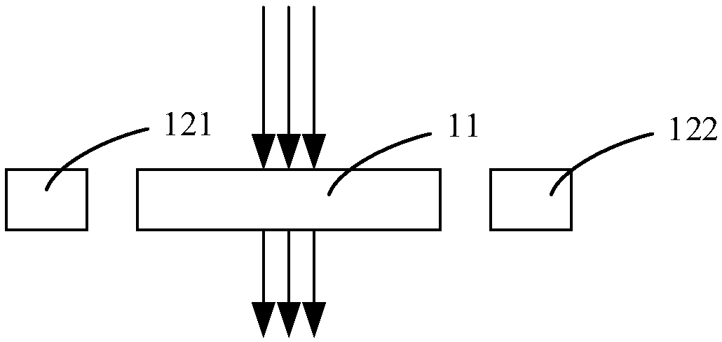
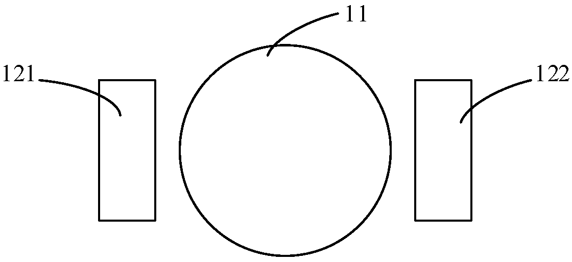
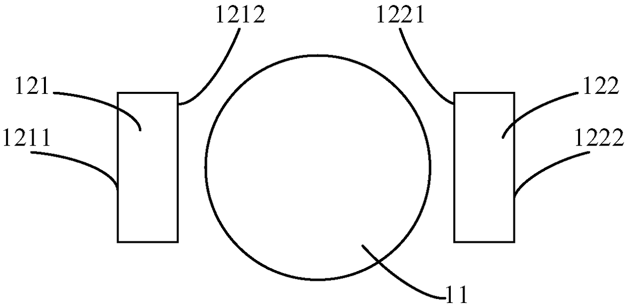
[0036] An embodiment of the present invention provides a high-field terahertz spin transmitter, including: a ferromagnetic nano-film with a preset size, a first magnet, and a second magnet;

[0037] Both the first magnet and the second magnet are fixed in the plane where the ferromagnetic nano-film is located, and the first magnet a...


PUM


Abstract

An embodiment of the invention provides a high-field Terahertz spinning emitter and a spectrometer. The high-field Terahertz spinning emitter comprises a ferromagnetic nanometer film in a preset sizeand first and second magnets; the first and second magnets are both fixed in the plane where the ferromagnetic nanometer film is fixed and are arranged in one straight line, a first pole of the firstmagnet is arranged opposite to a second pole of the second magnet, the polarity of the first pole is opposite to that of the second pole, and the ferromagnetic nanometer film is arranged between the first and second poles; and pumped laser in the preset pulse width with preset single pulse energy penetrates the ferromagnetic nanometer film to generate Terahertz pulse radiation in the preset spectral width and preset radiation field intensity. The high-field Terahertz spinning emitter can generate ultra-wideband high-field Terahertz pulse radiation, and overcome disadvantages when the high-field Terahertz pulse radiation is generated in the prior art.

Description

technical field [0001] The embodiments of the present invention relate to the technical field of terahertz pulse generation, and more particularly, to a strong-field terahertz spin transmitter and a spectrometer. Background technique [0002] Terahertz radiation is located between the far-infrared and millimeter waves on the electromagnetic spectrum. The special position of this frequency band endows this frequency band with special properties. For example, the terahertz frequency corresponds to the vibrational and rotational energy levels of biological macromolecules, and corresponds to the energy level of water molecules. Hydrogen bond energy and van der Waals force energy, many biomolecules have fingerprint spectra in this frequency band, which can be used in material identification and identification; the terahertz frequency band means greater information capacity, providing more information for communication, remote sensing, aerospace and aerospace. good means of commun...

Claims


Application Information

Patent Timeline
IPC IPC(8): G01J3/28G01J3/02G01J3/10G01N21/01
CPCG01J3/0208G01J3/10G01J3/28G01N21/01G01N2021/0112
Inventor 吴晓君聂天晓孔德胤高扬郭苡辰
Owner BEIHANG UNIV
Why Eureka
Try Eureka