Additive manufacturing method and device for large metal part

A technology for additive manufacturing and metal parts, which is applied in the field of additive manufacturing methods and devices for large metal parts, can solve the problems of inability to manufacture complex metal components, difficulty in controlling metallurgical defects, and high tonnage requirements of forging presses, and achieves reduction of residual stress. and deformation and cracking tendency, excellent mechanical properties, the effect of improving performance

Active Publication Date: 2018-12-18
HUAZHONG UNIV OF SCI & TECH
View PDF8 Cites 19 Cited by
  • Summary
  • Abstract
  • Description
  • Claims
  • Application Information

AI Technical Summary

Problems solved by technology

[0007] For large-shaped metal parts, there are cumbersome procedures, long processing cycle, and difficulty in controlling metallurgical defects when using traditional casting technology. When forging is used, there are high tonnage requirements for forging presses, high mold manufacturing costs, long processing cycles and inability to manufacture. Due to the difficulties of complex metal components and the insufficient forming efficiency of the existing additive manufacturing technology, the present invention proposes a high-performance, high-efficiency composite additive manufacturing technology for large metal parts that combines additive manufacturing technology, casting technology and forging technology. The material manufacturing method and device can realize high-performance, high-efficiency, and low-cost manufacturing of large metal parts, and have the advantages of high forming efficiency and good forming quality.

Method used


Image

  • Additive manufacturing method and device for large metal part
  • Additive manufacturing method and device for large metal part
  • Additive manufacturing method and device for large metal part

Examples


Embodiment 1

[0057] The production of super-large 304 stainless steel tubular parts, the outer diameter of the part is 1500mm, the inner diameter is 1200mm, and the length is 3000mm. The specific steps are as follows:

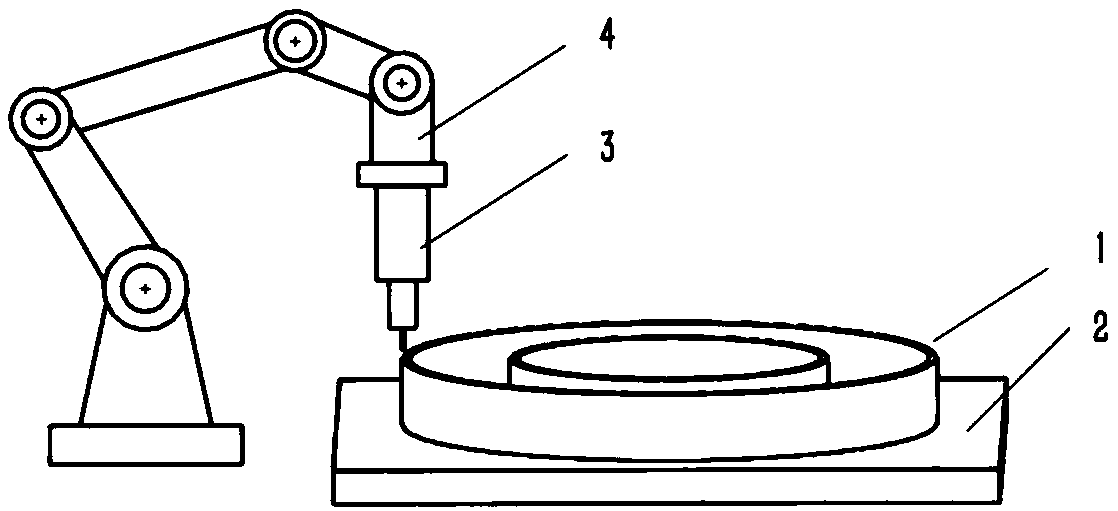
[0058] (1) Obtain the 3D CAD model of the part, slice the model, and then extract the data of the inner and outer contours of each layer, and generate the deposition path accordingly;

[0059] (2) Using arc additive manufacturing technology, several layers are deposited on the substrate according to the generated deposition path to form a metal cavity with a wall thickness of 10mm and a height of 50mm. The welding wire used in arc additive manufacturing is 304 stainless steel with a diameter of 1.2mm Welding wire, the welding current is 200A, the voltage is 20V, and the welding speed is 4.5mm / s;

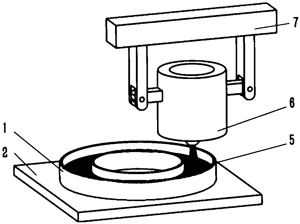
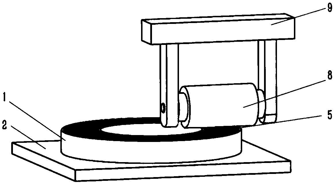
[0060] (3) The casting movement mechanism moves the casting equipment to the top of the metal cavity, injects the smelted 304 stainless steel into the metal cavity until it fills ...

Embodiment 2

[0064] The production of super-large tubular parts, the outer diameter of the part is 1500mm, the inner diameter is 1200mm, and the length is 3000mm. The surface layer of the part is 304 stainless steel, and the core is Q235. The specific steps are as follows:

[0065] (1) Obtain the 3D CAD data model of the part, slice the model, then extract the data of the inner and outer contours of each layer, and generate the deposition path;

[0066] (2) Using arc additive manufacturing technology, several layers are deposited on the substrate according to the generated deposition path to form a metal cavity with a wall thickness of 5 mm and a height of 10 mm. The arc additive manufacturing uses 304 stainless steel welding wire with a diameter of 1.2 mm. The current is 200A, the voltage is 20V, and the welding speed is 4.5mm / s;

[0067] (3) The casting movement mechanism moves the casting equipment to the top of the metal cavity, injects the smelted Q235 molten steel into the metal cavi...

Embodiment 3

[0071] Such as Figure 6 As shown, the production of large spherical parts, the outer diameter of the part is 1400mm, the inner diameter is 1000mm, and the material of the part is 316 stainless steel. The specific steps are as follows:

[0072] (1) Obtain the 3D CAD data model of the part, slice the model, then extract the data of the inner and outer contours of each layer, and generate the deposition path;

[0073](2) Using arc additive manufacturing technology, several layers are deposited on the substrate according to the generated deposition path to form a metal cavity with a wall thickness of 20 mm and a height of 70 mm. The welding wire used in arc additive manufacturing is 316 stainless steel with a diameter of 1.2 mm Welding wire, the welding current is 185A, the voltage is 20V, and the welding speed is 5.4mm / s;

[0074] (3) The casting movement mechanism moves the casting equipment to the top of the metal cavity, injects the smelted 316 stainless steel liquid into th...


PUM

PropertyMeasurementUnit
melting pointaaaaaaaaaa
thicknessaaaaaaaaaa

Abstract

The invention belongs to the field of additive manufacturing, and specifically discloses an additive manufacturing method and device for a large metal part. Firstly, the additive manufacturing technology is used, slice processing is performed according to a data model of the part, then contour data of all layers are extracted, a deposition path of a contour is generated, a metal cavity having a certain thickness and depth is manufactured on a substrate, smelted metal is injected into the metal cavity, after the smelted metal is in the solidification or semi-solidification state, the part is rolled and processed, deposition of a new metal cavity in the part is continuously carried out, and the above steps are continuously executed until the overall part is completed. The additive manufacturing method and device solve the defects that a current large-scale metal part wholly adopts the additive manufacturing process so that the efficiency can be insufficient and cracking can be easy, thecasting process is adopted so that defects such as contraction and shrinkage can exist, the shortcoming that the process is complicated and the cycle is too long and the shortcoming that the forging process is adopted so that a forging press can have the tonnage limit and the cycle can be too long, and the high-performance metal parts can be quickly manufactured with low cost.

Description

technical field [0001] The invention belongs to the field of additive manufacturing, and more specifically relates to a method and device for additive manufacturing of large metal parts. Background technique [0002] At present, the manufacturing methods of large metal parts mainly include forging, casting, machining, etc., or use forging and casting processes to form parts in sections, and then use welding processes or mechanical connections to form whole parts. After years of development, casting technology and large-scale forging equipment at home and abroad have made great progress, and the processed metal parts have been continuously improved in terms of volume and quality. However, large parts are prone to defects such as porosity, shrinkage cavity, and inclusions during the casting process; when forging large parts, there are problems such as insufficient tonnage of forging presses, high mold processing costs, cumbersome manufacturing processes, and long processing cy...

Claims


Application Information

Patent Timeline
Patent Type & Authority Applications(China)
IPC IPC(8): B22F3/105B22F5/10B22D19/00B22D27/11B33Y10/00B33Y50/00
CPCB23P15/00B22F3/105B22D19/00B22D27/11B22F3/003B22F5/10B33Y10/00B33Y30/00B33Y50/00
Inventor 曾晓雁曹嘉明高明
Owner HUAZHONG UNIV OF SCI & TECH
Why Eureka
Try Eureka