Accident-resistant fuel core cladding tube and preparation method thereof
A core cladding tube and fuel technology, which is applied in the field of accident-resistant fuel nuclear cladding tubes and their preparation, can solve problems such as reducing the mechanical properties of the cladding tubes, overcome catastrophic accidents, alleviate thermal expansion coefficient mismatches, and prevent interfacial reactions. Effect
- Summary
- Abstract
- Description
- Claims
- Application Information
AI Technical Summary
Problems solved by technology
Method used
Image
Examples
Embodiment 1
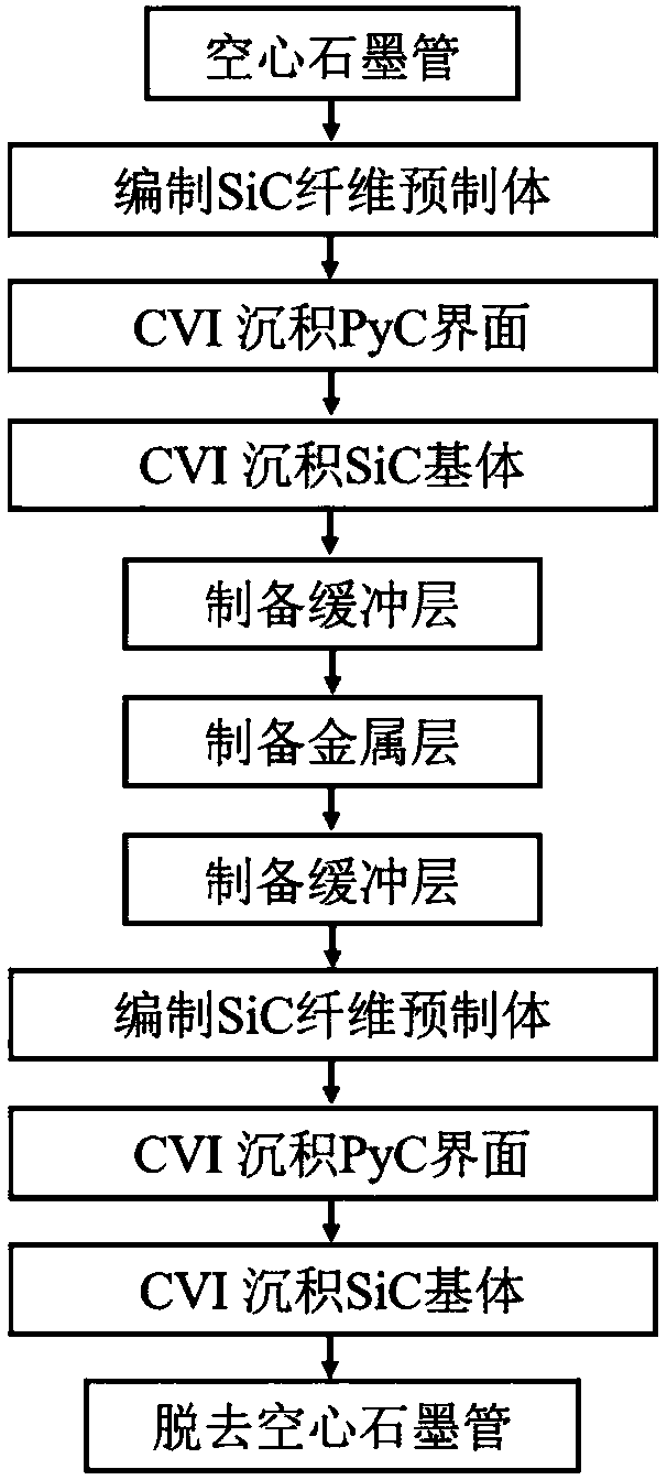
[0057] (1) A SiC fiber preform with a thickness of 400 μm is braided outside a hollow graphite tube with a diameter of 9 mm. Then the obtained SiC fiber prefabricated body was hung on the supporting sample holder of the vacuum furnace, and the prefabricated body was located in the center of the isothermal zone in the furnace, and the PyC interface was deposited on the above SiC fiber by CVI process. Deposition process parameters: precursor gas source adopts propylene (C 3 h 6 ), the deposition temperature is 800°C, the deposition pressure is 2kPa, the deposition is 20h, and the PyC interface with a thickness of 100nm is deposited. Finally, trichloromethylsilane (CH 3 SiCl 3 , MTS), hydrogen (H 2 ) and diluent gas argon (Ar), where H 2 The molar mixing ratio with MTS is 10:1. Keep the pressure in the furnace at 2kPa, deposit the SiC matrix in the temperature range of 1000°C, and the deposition time is 400h.
[0058] (2) Grinding the outer surface of the inner tube layer ...
Embodiment 2
[0063] (1) A SiC fiber preform with a thickness of 300 μm is braided outside a hollow graphite tube with a diameter of 9 mm. Then the obtained SiC fiber prefabricated body was hung on the supporting sample holder of the vacuum furnace, and the prefabricated body was located in the center of the isothermal zone in the furnace, and the PyC interface was deposited on the above SiC fiber by CVI process. Deposition process parameters: precursor gas source adopts propylene (C 3 h 6 ), the deposition temperature is 900°C, the deposition pressure is 2kPa, the deposition is 30h, and the PyC interface with a thickness of 200nm is deposited. Finally, trichloromethylsilane (CH 3 SiCl 3 , MTS), hydrogen (H 2 ) and diluent gas argon (Ar), where H 2 The molar mixing ratio with MTS is 10:1. Keep the pressure in the furnace at 2kPa, deposit the SiC substrate at a temperature range of 900°C, and the deposition time is 300h.
[0064](2) Grinding the outer surface of the inner tube layer w...
Embodiment 3
[0069] (1) A SiC fiber preform with a thickness of 300 μm is braided outside a hollow graphite tube with a diameter of 9 mm. Then the obtained SiC fiber prefabricated body was hung on the supporting sample holder of the vacuum furnace, and the prefabricated body was located in the center of the isothermal zone in the furnace, and the PyC interface was deposited on the above SiC fiber by CVI process. Deposition process parameters: precursor gas source adopts propylene (C 3 h 6 ), the deposition temperature is 800°C, the deposition pressure is 2kPa, the deposition is 20h, and the PyC interface with a thickness of 100nm is deposited. Finally, trichloromethylsilane (CH 3 SiCl 3 , MTS), hydrogen (H 2 ) and diluent gas argon (Ar), where H 2 The molar mixing ratio with MTS is 10:1. Keep the pressure in the furnace at 2kPa, deposit the SiC matrix in the temperature range of 1000°C, and the deposition time is 400h.
[0070] (2) Grinding the outer surface of the inner tube layer ...
PUM
| Property | Measurement | Unit |
|---|---|---|
| Roughness | aaaaa | aaaaa |
Abstract
Description
Claims
Application Information
 - R&D
- Intellectual Property
- Life Sciences
- Materials
- Tech Scout
- Unparalleled Data Quality
- Higher Quality Content
- 60% Fewer Hallucinations
Browse by: Latest US Patents, China's latest patents, Technical Efficacy Thesaurus, Application Domain, Technology Topic, Popular Technical Reports.
© 2025 PatSnap. All rights reserved.Legal|Privacy policy|Modern Slavery Act Transparency Statement|Sitemap|About US| Contact US: help@patsnap.com


