
An oxide-based thin film transistor type ultraviolet detector and a preparation method thereof

A technology of thin-film transistors and ultraviolet detectors, applied in the field of ultraviolet detectors, can solve the problems of increasing manufacturing complexity and reducing performance, and achieve the effects of improving photoelectric conversion ability, increasing electrical conductivity, and improving response time

Pending Publication Date: 2018-12-18
DONGGUAN UNIV OF TECH
View PDF0 Cites 0 Cited by
  • Summary
  • Abstract
  • Description
  • Claims
  • Application Information

AI Technical Summary

Problems solved by technology

Silicon-based UV photocells require accompanying filters, which undoubtedly increases manufacturing complexity and degrades performance

Method used


Image

  • An oxide-based thin film transistor type ultraviolet detector and a preparation method thereof
  • An oxide-based thin film transistor type ultraviolet detector and a preparation method thereof
  • An oxide-based thin film transistor type ultraviolet detector and a preparation method thereof

Examples


Embodiment 1

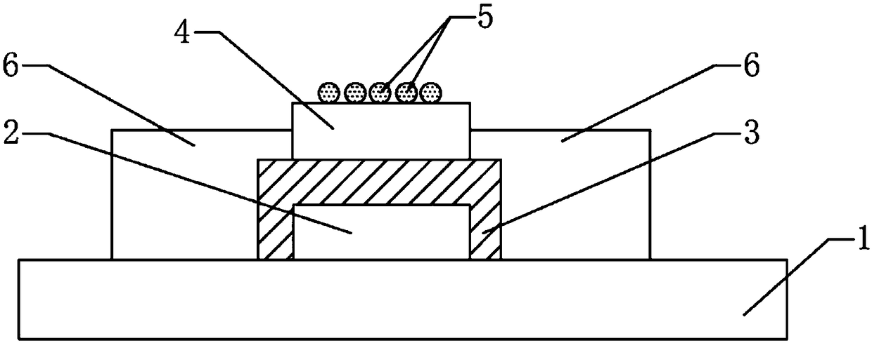
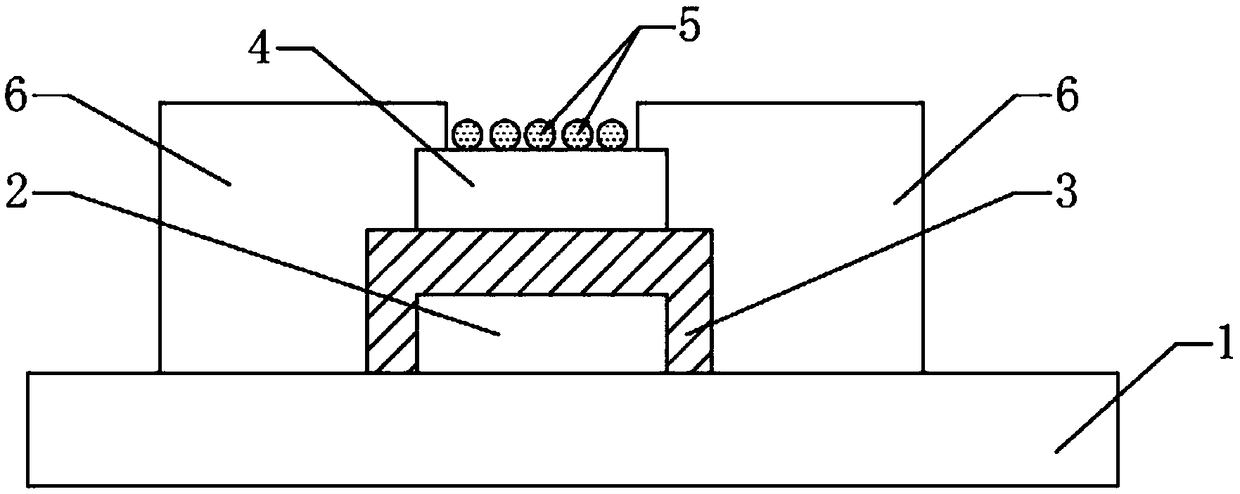
[0047] See figure 1 , an oxide-based thin film transistor type ultraviolet detector, comprising a substrate 1, a composite layer arranged on the upper surface of the substrate, and metal electrodes 6 symmetrically clamped on both sides of the composite layer; the composite layer Including electrode layer 2, SiO 2 / Si 3 N 4 Composite insulating layer 3, IGZO channel layer 4 and nano metal particles 5, the lower surface of the electrode layer 2 is connected to the upper surface of the substrate 1, the SiO 2 / Si 3 N 4 The composite insulating layer 3 is coated on the surface of the electrode layer 2 in an inverted buckle shape, and the IGZO channel layer 4 is arranged on the SiO 2 / Si 3 N 4 The upper surface of the composite insulating layer 3, the nano-metal particles 5 are distributed on the upper surface of the IGZO channel layer 4; the SiO 2 / Si 3 N 4 Both sides of the composite insulating layer 3 and both sides of the IGZO channel layer 4 are connected to the metal...

Embodiment 2

[0062] The difference between this embodiment and above-mentioned embodiment 1 is:

[0063] The stabilizer is polyethylene glycol, and the solvent is ethylene glycol methyl ether.

[0064] In the step A, the ultrasonic treatment frequency is 100 kHz, and the ultrasonic treatment time is 8 min; the stirring speed is 800 rpm, and the stirring time is 18 h.

[0065] Step A1 is also included after step A: filter the IGZO precursor prepared in step A through a filter head with a pore size of 0.15-0.21 μm, and then age for 18 hours to obtain a stable IGZO precursor.

[0066] In the step C, the rotational speed of the spin coating is 4800 rpm, the spin coating time is 28 s, the annealing temperature is 300° C., and the annealing time is 7 min.

Embodiment 3

[0068] The difference between this embodiment and above-mentioned embodiment 1 is:

[0069] The stabilizer is ethanolamine, and the solvent is ethylene glycol methyl ether.

[0070] In the step A, the ultrasonic treatment frequency is 150 kHz, and the ultrasonic treatment time is 12 minutes; the stirring speed is 1000 rpm, and the stirring time is 12 hours.

[0071] Step A1 is also included after the step A: filter the IGZO precursor prepared in step A through a filter head with a pore size of 0.15-0.21 μm, and then age for 24 hours to obtain a stable IGZO precursor.

[0072] In the step C, the rotational speed of the spin coating is 5000 rpm, the spin coating time is 25 s, the annealing temperature is 400° C., and the annealing time is 6 min.


PUM

PropertyMeasurementUnit
electrical resistivityaaaaaaaaaa
particle diameteraaaaaaaaaa

Abstract

The invention relates to the technical field of ultraviolet detectors, in particular to an oxide-based thin film transistor-type ultraviolet detector and a preparation method thereof. The ultravioletdetector comprises a substrate, a composite layer arranged on the upper surface of the substrate, and metal electrodes symmetrically clamped on both sides of the composite layer. The composite layer comprises an electrode layer, a SiO2 / Si3N4 composite insulating layer, an IGZO channel layer and nanometer metal particles. The SiO2 / Si3N4 composite insulating layer is inverted on the surface of the electrode layer. A low surface of that metal electrode is connected with an upper surface of the substrate; The distribution density of nanometer metal particles on the upper surface of IGZO channel layer is 1*106-1*1012 / cm<2>. The ultraviolet detector of the invention adopts the special structure of the thin film transistor type, and the dark current is small. When the ultraviolet light is irradiated, the IGZO channel layer can absorb the ultraviolet light to generate optical carriers, thereby forming a larger source-drain current, forming the photocurrent of the ultraviolet detector, and having high ultraviolet detection sensitivity.

Description

technical field [0001] The invention relates to the technical field of ultraviolet detectors, in particular to an oxide-based thin film transistor type ultraviolet detector and a preparation method thereof. Background technique [0002] Ultraviolet detection is a new technology based on the detection of atmospheric transmission and attenuation of ultraviolet radiation and high-performance ultraviolet optical sensors. It has a wide range of applications, including automatic control, flame monitoring, pollution monitoring, ozone monitoring, etc. , and in the fields of UV alarm, UV communication, spacecraft monitoring, identification of cosmic ray monitoring, space communication, positioning welding, and engine monitoring working in extremely harsh environments in the most advanced military technology. [0003] Although there is an urgent need for ultraviolet detectors in both military and civilian applications, the mainstream photomultiplier tubes and silicon-based ultraviolet...

Claims


Application Information

Patent Timeline
Patent Type & Authority Applications(China)
IPC IPC(8): H01L31/113H01L31/18
CPCH01L31/1136H01L31/18Y02P70/50
Inventor 张耿刘敏霞王红成张绍强郑华
Owner DONGGUAN UNIV OF TECH
Learn More