
A method for manufacture a flexible transparent electromagnetic shielding film by 3D printing

An electromagnetic shielding film, 3D printing technology, applied in the fields of magnetic/electric field shielding, electrical components, additive processing, etc., can solve the problem of difficulty in manufacturing high-performance flexible transparent electromagnetic shielding films, flexible substrates that are easily damaged by heat, and nano-metals that are easily damaged. Oxidation and other problems, to achieve the effect of super electromagnetic shielding performance, wide application range and low manufacturing cost

Active Publication Date: 2018-12-18
QINGDAO TECHNOLOGICAL UNIVERSITY
View PDF10 Cites 12 Cited by
  • Summary
  • Abstract
  • Description
  • Claims
  • Application Information

AI Technical Summary

Problems solved by technology

For example, the existing lithography, nanoimprinting, inkjet printing, electrojet printing, etc. all face great challenges and deficiencies in realizing ultra-fine line width and high aspect ratio metal grid structures.
In addition, no matter which technology is used, the nano-metal paste used in the manufacture of metal grids must be sintered to have good electrical conductivity. Since polymer flexible substrates generally have poor heat resistance, it is difficult to sinter nano-metal pastes. The flexible substrate is easily damaged by heat when the slurry is used, and the nano-metal is also prone to oxidation during sintering
[0005] Therefore, the existing technology has deficiencies in the manufacture of flexible transparent electromagnetic shielding films, and it is still difficult to manufacture high-performance flexible transparent electromagnetic shielding films with high light transmittance (ultra-fine line width) and strong electromagnetic shielding efficiency (large aspect ratio). Shielding film

Method used


Image

  • A method for manufacture a flexible transparent electromagnetic shielding film by 3D printing
  • A method for manufacture a flexible transparent electromagnetic shielding film by 3D printing
  • A method for manufacture a flexible transparent electromagnetic shielding film by 3D printing

Examples


Embodiment 1

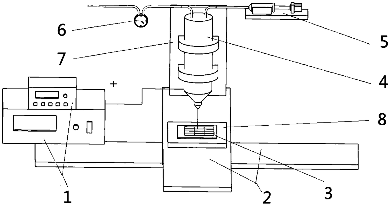
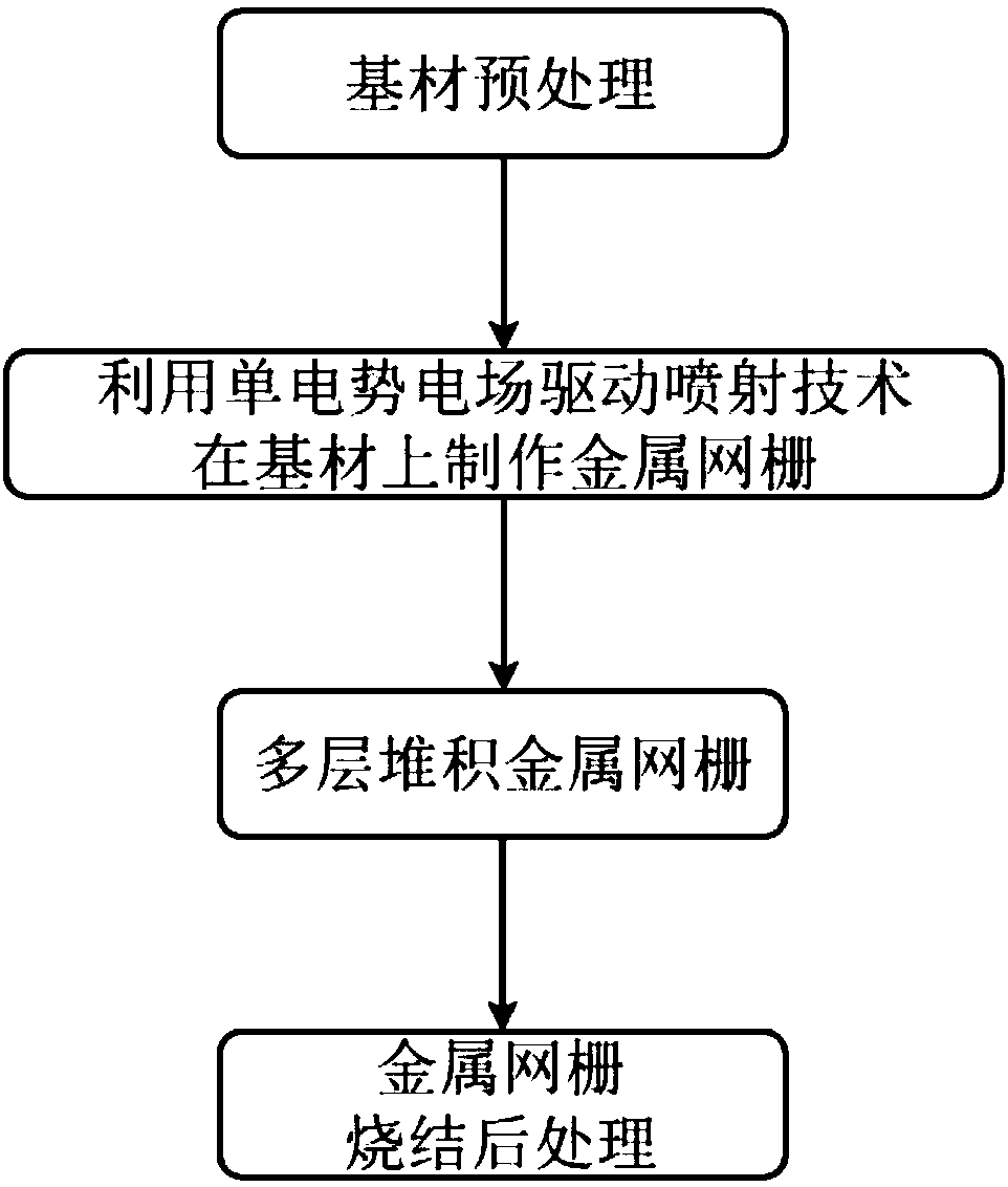
[0057] In this embodiment, the PET of 100x100mm is used as the base material, the particle-free nano-silver paste (containing more than 20% silver) that can be sintered at low temperature is used as the printing material, the hard substrate 3 is glass, and the gold-sprayed glass needle is used as the nozzle. The production cycle of the electric field-driven jet deposition 3D printing equipment is 200 microns, the line width is 2 microns, and the metal grid with an aspect ratio of 1:1. The working principle of the electric field-driven 3D printing equipment is as follows: figure 1 As shown, the manufacturing process is as follows figure 2 As shown, the specific steps include:

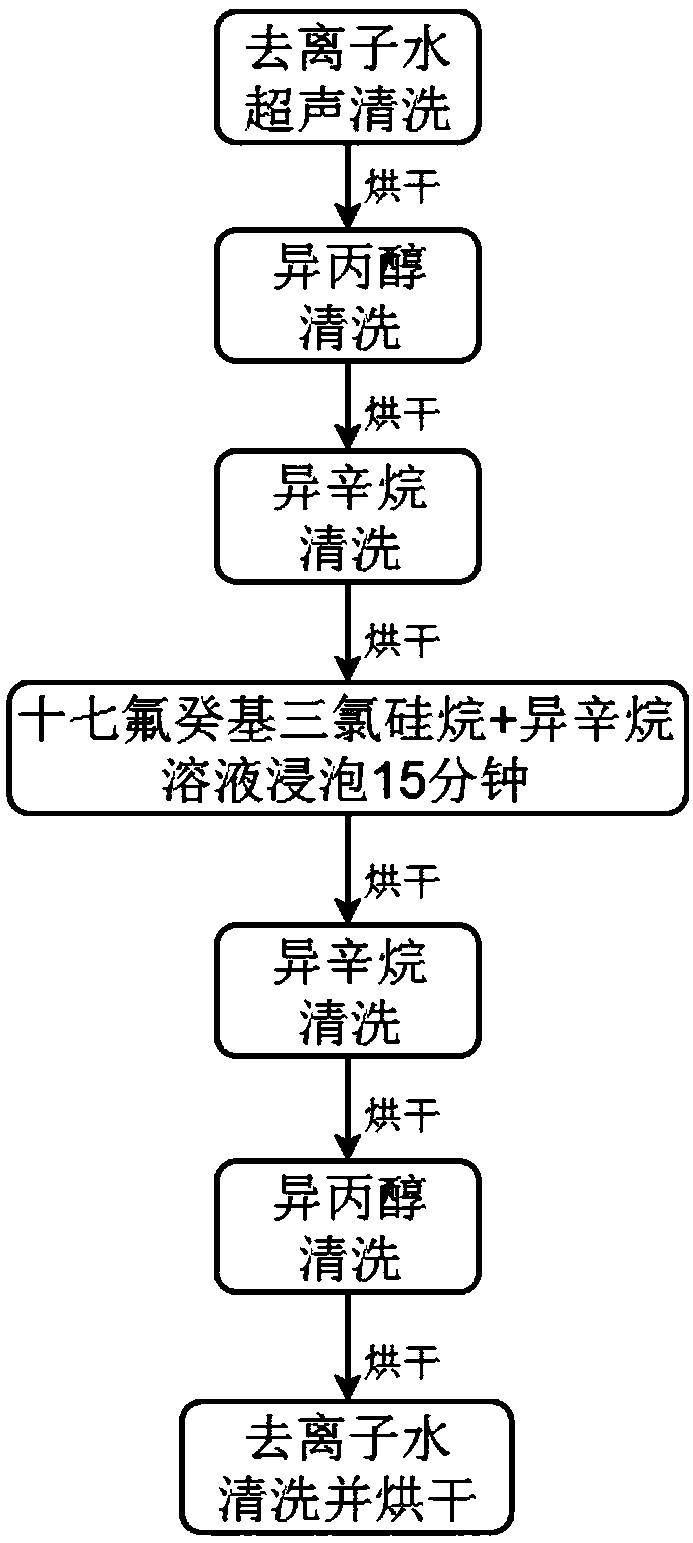
[0058] Step 1: Substrate pretreatment. according to image 3 Process, pretreatment of PET film substrates, including: deionized water ultrasonic cleaning, isopropanol cleaning, isooctane cleaning, heptadecafluorodecyltrichlorosilane + isooctane solution soaking for 15 minutes, isooctane Rinse, rinse ...

Embodiment 2

[0062] In this embodiment, 200x200mm PEN is used as the base material, conductive silver glue is used as the printing material, and the hard substrate 3 is glass. The production cycle of the 3D printing equipment driven by electric field is 150 microns, the line width is 5 microns, and the aspect ratio is 2: 1 metal grid, the working principle of electric field driven 3D printing equipment is as follows figure 1 As shown, the manufacturing process is as follows figure 2 As shown, the specific steps include:

[0063] Step 1: Substrate pretreatment. according to image 3 Process, pretreatment of the PEN substrate, including: deionized water ultrasonic cleaning, isopropanol cleaning, isooctane cleaning, heptadecafluorodecyltrichlorosilane + isooctane solution soaking for 15 minutes, isooctane cleaning , isopropanol cleaning, deionized water cleaning and drying.

[0064] Step 2: 3D print the metal grid. The pretreated PEN film base material is pasted and clamped on the hard ...

Embodiment 3

[0067] In this embodiment, PET with a size of 150x150 mm is used as the base material, nano conductive silver paste that can be sintered at low temperature is used as the printing material, and the hard substrate 3 is glass. The production cycle of the 3D printing equipment driven by electric field is 250 microns, and the line width is 7 microns. The working principle of electric field-driven 3D printing equipment with a metal grid with an aspect ratio of 1:1 is figure 1 As shown, the manufacturing process is as follows figure 2 As shown, the specific steps include:

[0068] Step 1: Substrate pretreatment. according to image 3 Process, pretreatment of PET film substrates, including: deionized water ultrasonic cleaning, isopropanol cleaning, isooctane cleaning, heptadecafluorodecyltrichlorosilane + isooctane solution soaking for 15 minutes, isooctane Rinse, rinse with isopropanol, rinse with deionized water, and dry.

[0069] Step 2: 3D print the metal grid. The pretreat...


PUM

PropertyMeasurementUnit
widthaaaaaaaaaa

Abstract

A method for manufacture a flexible transparent electromagnetic shielding film by 3D printing includes cleaning and drying a flexible transparent film base material to reduce surface energy; The pretreated flexible transparent film-like substrate is laminated and clamped and fixed on a hard substrate, A 3D spray deposition printing device driven by an electric field is used, a gold spray glass needle is use as a nozzle, a low-temperature sintered non-granular nano silver paste is used as a printing material, and a multi-layer metal mesh is printing on that surface of the pretreated substrate according to a predetermined path to obtain a desired printing height; A substrate of that manufacture metal mesh is vacuum-pumped or an inert gas atmosphere is construct, and a corresponding temperature and a corresponding time are set according to the used prin material, and the conductive treatment of sintering or drying is carried out. The invention not only can realize the manufacture of electromagnetic shielding film influenced by strong electromagnetic shielding efficiency, high light transmittance and low imaging quality, but also can shield electromagnetic waves of different wave bandsby adjusting the mesh period, and has good adaptability and flexibility.

Description

technical field [0001] The invention relates to a method for manufacturing a flexible transparent electromagnetic shielding film by 3D printing. Background technique [0002] The flexible transparent electromagnetic shielding film is suitable for anti-electromagnetic interference and all windows with transmittance requirements. It can effectively block the radiation of various electromagnetic waves, prevent information leakage, ensure information security, and ensure the stable and reliable use of equipment. It has a wide range of applications in many fields. Very wide range of applications, typical application areas include: (1) Electromagnetic interference and information leakage: display windows of various precision instruments and meters in the fields of communication, medical treatment, and electronic information, window shielding of glass doors and windows in secret rooms, shielding cabinets, etc.; 2) EMC needs of national defense and military products: window shieldin...

Claims


Application Information

Patent Timeline
Patent Type & Authority Applications(China)
IPC IPC(8): H05K9/00B22F3/11B22F3/22B33Y10/00
CPCB22F3/1103B22F3/22B33Y10/00H05K9/0086
Inventor 兰红波周贺飞赵佳伟许权
Owner QINGDAO TECHNOLOGICAL UNIVERSITY
Learn More