A high gain circularly polarized antenna

A circularly polarized antenna and high-gain technology, which is applied in antennas, antenna arrays, antenna arrays that are powered independently, etc., can solve the problems of leakage wave effect, difficult processing, and difficulty, and achieve easy disassembly and low processing difficulty , the effect of easy transportation

Inactive Publication Date: 2018-12-21
DONGGUAN UNIV OF TECH
View PDF4 Cites 1 Cited by
  • Summary
  • Abstract
  • Description
  • Claims
  • Application Information

AI Technical Summary

Problems solved by technology

[0003] 1. Waveguide slot antenna: This type of antenna is slotted on the wide or narrow side of the waveguide. Usually, there are two array forms of traveling wave and standing wave, but the gain of the radiating unit slot is relatively low, usually only about 7dB. In the form of series feed, there is a frequency sweep phenomenon within the bandwidth. With the increase of the working frequency, the processing accuracy is required to be higher, and it needs to be processed and manufactured with the help of a higher welding process. Polarized co-aperture radiation is more difficult
[0004] 2. Microstrip patch antenna, which has a low profile, can integrate active devices, and can realize the integrated design of the radiation unit and the network, but the dielectric loss of the antenna is large, and there is a leaky wave effect, and the gain of the antenna unit is low , Feed network loss is large, do not use to achieve high-gain antenna design
[0005] 3. Reflecting surface antenna, this type of antenna has good radio frequency performance in the Ka frequency band, low loss, high radiation efficiency, and relatively simple technology to achieve circular polarization radiation, but this type of antenna has a large physical size and is not suitable for some Where space is limited
[0006] 4. Lens antenna, the form of the antenna is similar to that of the reflector antenna. Usually, a feed source is used to irradiate a dielectric ball, a dielectric cake, etc. to focus the beam and achieve the purpose of high-gain irradiation. However, the same antenna size as the reflector antenna is too large. The function of beam adjustment cannot be realized
[0007] The invention patent with the application number 201610099961 .1 basically solves the above problems, but the device in this application is an integrated design, which requires high manufacturing process, difficult processing and inconvenient rapid assembly of the planar array radiation unit

Method used


Image

  • A high gain circularly polarized antenna
  • A high gain circularly polarized antenna
  • A high gain circularly polarized antenna

Examples


Embodiment Construction

[0019] In order to make the purpose, technical solutions and advantages of the embodiments of the present invention clearer, the technical solutions in the embodiments of the present invention will be clearly and completely described below in conjunction with the drawings in the embodiments of the present invention. Obviously, the described embodiments It is a part of embodiments of the present invention, but not all embodiments. Based on the embodiments of the present invention, all other embodiments obtained by persons of ordinary skill in the art without creative efforts fall within the protection scope of the present invention.

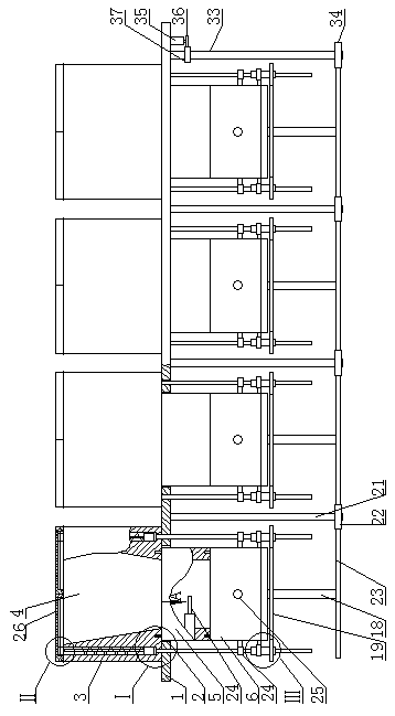
[0020]A high-gain circularly polarized antenna, as shown in the figure, includes a horizontal mounting plate 1, a plurality of evenly distributed circular holes 2 are opened on the top surface of the mounting plate 1, and a first cylindrical body 3 is provided at the upper end of the circular holes 2. The inside of a cylinder 3 is a trumpet-shaped...


PUM


Abstract

A high gain circularly polarized antenna including transverse mounting plates, A plurality of evenly distributed round holes are arranged on the top surface of the mounting plate, An upper end of thatround hole is provide with a first cylinder, the inner part of the first cylinder is a trumpet-shaped cavity with a large upper end and a small lower end, the lower end of the first cylinder is provided with a second cylinder, The upper end of the second cylinder body is inserted into the corresponding circular hole, and the lower end of the second cylinder body is provided with a third cylinderbody, the first cylinder body, the second cylinder body and the third cylinder body are coaxial in the same vertical direction, the second cylinder body is a low-frequency resonant cavity, the third cylinder body is a high-frequency resonant cavity, and the low-frequency resonant cavity and the high-frequency resonant cavity are both elliptical cylinders. The upper port of the horn-shaped cavity is closed at any time by two semi-circular cover plates which are matched, so that external impurities can be avoided to enter the low-frequency resonant cavity and the high-frequency resonant cavity,thereby affecting the stability of the signal emitted by the invention. The invention simplifies the processing technology, reduces the manufacturing difficulty and reduces the production cost throughthe modular design.

Description

technical field [0001] The invention belongs to the technical field of antennas, in particular to a high-gain circularly polarized antenna. Background technique [0002] At present, the communication frequency band is more and more developing towards the high frequency band, especially in the Ku and Ka bands. The frequency determines the bandwidth ratio of the antennas working in the L and S bands. The antennas required to work in this frequency band have small size, high gain, and spot beams. In particular, the distance between the transmitting and receiving working frequency bands is relatively long, the antenna needs dual-frequency operation, and circularly polarized radiation is required. The antennas that achieve the above performance mainly include the following types of antennas, but each has its own advantages and disadvantages. [0003] 1. Waveguide slot antenna: This type of antenna is slotted on the wide or narrow side of the waveguide. Usually, there are two arra...

Claims


Application Information

Patent Timeline
Patent Type & Authority Applications(China)
IPC IPC(8): H01Q1/12H01Q1/36H01Q1/42H01Q1/50H01Q15/24H01Q21/00H01Q21/06
CPCH01Q1/12H01Q1/36H01Q1/42H01Q1/50H01Q15/24H01Q21/0006H01Q21/06
Inventor 曾淼旺
Owner DONGGUAN UNIV OF TECH
Why Eureka
Try Eureka