Adaptive synchronous rectification control system and control method for active clamp flyback converter

A flyback converter and synchronous rectification technology, applied in control/regulation systems, DC power input conversion to DC power output, instruments, etc., can solve the problem that the efficiency of the active clamp flyback converter cannot be improved and the body diode loss is large , Sampling resistance loss and other problems, to achieve the effect of improving self-adaptive adjustment ability, attenuating oscillation, and improving system efficiency

Active Publication Date: 2019-11-22
SOUTHEAST UNIV
View PDF8 Cites 0 Cited by
  • Summary
  • Abstract
  • Description
  • Claims
  • Application Information

AI Technical Summary

Problems solved by technology

Among the three synchronous rectifier control schemes, the method of detecting current has high precision, but the sampling resistor has a large loss and is gradually eliminated; detecting the power supply voltage cannot avoid the conduction of the parasitic body diode of the synchronous rectifier, and when the PCB around the synchronous rectifier When the parasitic inductance of the wiring is too large, it is easy to cause the premature shutdown time to be too long, resulting in a large loss of the body diode; the existing adaptive synchronous rectification control scheme using digital control can effectively reduce the parasitic body of the synchronous rectifier However, the turn-off point of the synchronous rectifier still lingers between whether the body diode is on or not, and it is impossible to find a suitable turn-off point, so the synchronous rectifier cannot be turned off at the exact point, and the Unable to improve the efficiency of the active clamp flyback converter

Method used


Image

  • Adaptive synchronous rectification control system and control method for active clamp flyback converter
  • Adaptive synchronous rectification control system and control method for active clamp flyback converter
  • Adaptive synchronous rectification control system and control method for active clamp flyback converter

Examples


specific Embodiment 1

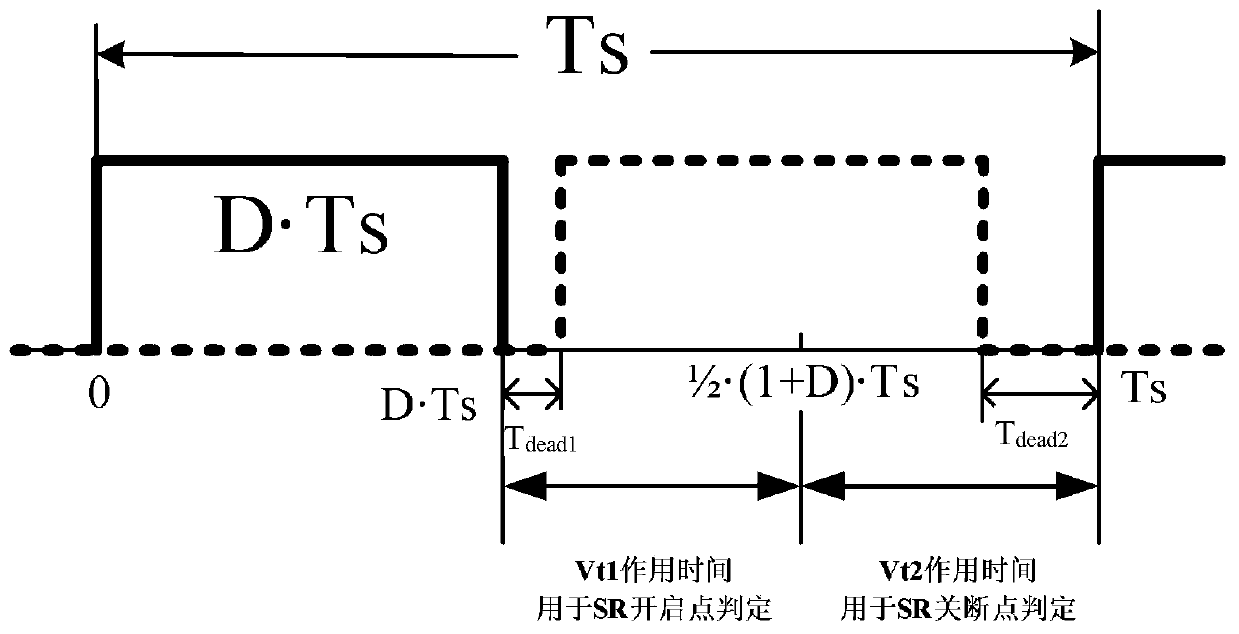
[0051] This embodiment combines image 3 the first threshold V on the non-inverting input of the first comparator t1 and the second threshold V t2 The schematic diagram of the action time period and the state detection time of the synchronous rectifier, and the technical scheme of the time-division multiplexing of the first comparator for the state detection of the synchronous rectifier is described in detail, as follows:

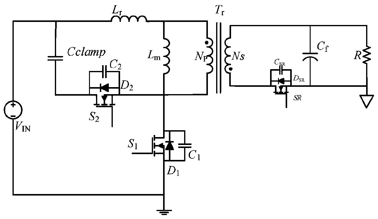
[0052] use figure 1 As shown in the active clamp flyback converter, define its primary side main power transistor S 1 The gate drive signal V gsThe duty cycle is D, and one duty cycle of the active clamp flyback converter is defined as T s , that is, the main power tube S 1 A duty cycle of T s , then the main power tube S 1 The conduction period is expressed as: T on =D×T s ; Main power tube S 1 The off-time period is expressed as: T off =(1-D)×T s . Primary side main power tube S 1 The gate drive signal V gs Such as image 3 As shown by the...

specific Embodiment 2

[0057] In this embodiment, the logic flow for detection and control of the on-state of the secondary synchronous rectifier when the primary side power tube of the active clamp flyback converter uses Si devices, and the primary side power tube of the active clamp flyback converter uses GaN devices The logic flow of the on-state detection and control of the synchronous rectifier tube on the secondary side is described in detail.

[0058] When the primary side power transistor of the active clamp flyback converter uses Si devices, in the current duty cycle During the time period, the logic flow of the detection and control of the on-state of the secondary synchronous rectifier is as follows: Figure 4 As shown, the details are as follows:

[0059] Step A-1. The control unit judges the clamping tube S on the primary side 2 Whether conduction: primary side clamp tube S 2 conduction, enter step A-2; the primary side clamp tube S 2 off, repeat step A-1;

[0060] Step A-2, prima...

specific Embodiment 3

[0072] This embodiment combines Figure 6 , to carry out a detailed description of the off-state detection of the secondary side synchronous rectifier tube of the active clamp flyback converter and the control logic of the next cycle on-time, as follows:

[0073] Step C-1, in the current working cycle During the time period, the first sensing voltage V after the synchronous rectifier is turned off by using the first comparator SR1 and the second threshold V t2 Perform comparison and logic judgment: when the synchronous rectifier is turned off, the first sensing voltage signal V SR1 less than the second threshold V t2 , A is high level; the first sensing voltage signal V SR1 greater than the second threshold V t2 When , A is low level;

[0074] Step C-2, using the second comparator to turn off the second sensing voltage V after the synchronous rectifier is turned off SR2 and the third threshold V t3 Compare and output signal B: After the synchronous rectifier is turned...


PUM


Abstract

The invention discloses an adaptive synchronous rectification control system and a control method of an active clamp flyback converter; the control system includes a sampling and signal processing circuit, a control circuit with a microcontroller as the core and a gate driver; the control method can Realize the direct detection of the on-state, early-off, late-off, and just-off states of the synchronous rectifier on the secondary side of the active clamp flyback converter, and can control the accurate turn-on of the synchronous rectifier and the next step according to the detection results The conduction time of the synchronous rectifier in the cycle. After several cycles of self-adaptive control, the synchronous rectifier enters the exactly off state, which avoids the oscillation of the output waveform of the active clamp flyback converter, reduces the loss, and improves the efficiency; according to different state detection time periods, it is divided into The comparator inside the microcontroller is multiplexed in time, which saves hardware resources and reduces circuit cost and debugging difficulty.

Description

technical field [0001] The invention relates to an adaptive synchronous rectification control system and method, in particular to an adaptive synchronous rectification control system and a control method of an active clamp flyback converter. Background technique [0002] In the application occasion of the low-power converter, the flyback converter is one of the commonly used topologies. In recent years, since the active clamp flyback converter has the advantages of using leakage inductance energy to achieve soft switching, a duty cycle greater than 0.5, and higher operating frequency and efficiency, it has gradually become a low-power converter to improve power density, switching frequency and efficient solution. [0003] In the prior art, a synchronous rectifier is used to replace the diode in the secondary loop of the active clamp flyback converter, which can reduce the conduction loss of the secondary diode and greatly improve the efficiency of the converter. However, d...

Claims


Application Information

Patent Timeline
Patent Type & Authority Patents(China)
IPC IPC(8): H02M3/335
CPCH02M3/33592H02M1/342Y02B70/10H02M1/08H02M1/0048
Inventor 钱钦松许胜有刘琦孙伟锋陆生礼时龙兴
Owner SOUTHEAST UNIV
Why Eureka
Try Eureka