Hot-melt laminated decorative laminate

A technology of decorative layer and hot-melt layer, applied in the direction of lamination device, lamination, decoration, etc., can solve unsatisfactory problems such as unsatisfactory solutions, improve process economy, reduce solvent pollution emissions, high The effect of abrasion resistance

Inactive Publication Date: 2018-12-21
PROFOL KUNSTE
View PDF7 Cites 3 Cited by
  • Summary
  • Abstract
  • Description
  • Claims
  • Application Information

AI Technical Summary

Problems solved by technology

[0009] Provides an adhesive that exhibits very good adhesion between layers and is substantially free of hazardous substances, in particular vinyl chloride monomer, and requires only a mini

Method used


Image

  • Hot-melt laminated decorative laminate
  • Hot-melt laminated decorative laminate
  • Hot-melt laminated decorative laminate

Examples


Embodiment 1

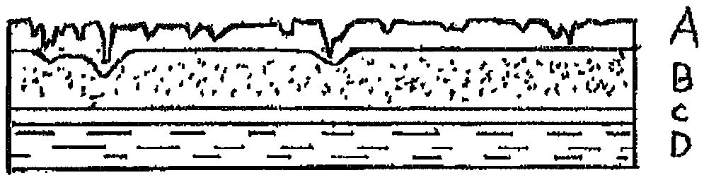
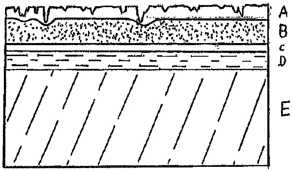
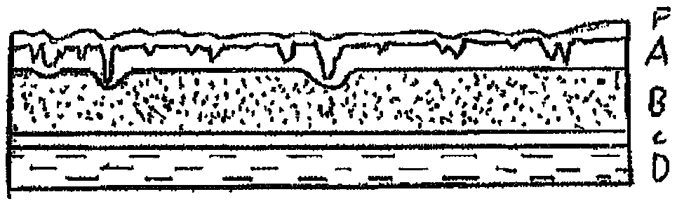
[0096] A structured decorative laminate with the following layer sequence was produced according to the method of the invention, wherein layers A, B and C were coextruded at 250°C, then still at 230°C and a linear load of 14.5kN / m (145N / cm) Immediately hot melt laminated with polypropylene layer D (with wood grain pattern printed on casein ink and provided with primer) with embossed plastic wood grain pattern on the visible side (mold engraved surface of embossing roll is rough Degree R Z is 120 μm), thus obtaining a structured decorative laminate according to the invention.

[0097] Layer A (50 μm) 95% by weight ionomer (DuPont’s 1706), 5% by weight of silicon dioxide with a particle size of 2-50 μm (95%);

[0098] Layer B (230 μm) 85% by weight ionomer (DuPont’s 1706) and 15% by weight of metallocene polyethylene;

[0099] Layer C (20 μm) maleic anhydride modified polyethylene as modified plastic for connection;

[0100] Layer D (120 μm including primer up to 10 μm) w...

Embodiment 3

[0116] In Example 3, the same sequence of layers ABC as in Example 1 was coextruded at 250°C and then immediately with the same Polypropylene layer D (with a wood grain pattern printed with casein ink and provided with a primer) was hot melt laminated. The resulting decorative laminate was cooled to room temperature and reheated in a subsequent step to 125°C, at which temperature the plastic wood was embossed using the same embossing roll as in Example 1 and under the same linear load. grain pattern to obtain a structured decorative laminate.

[0117] Determination of embossing depth index I after cooling P . For this purpose, the corresponding roughnesses of Example 1 of hot-melt embossing according to the present invention and Example 3 of subsequent embossing were measured at five matching points of embossing. Roughness and embossing depth index I even before holding at high temperature P Significant differences were also measurable (Table 2).

[0118] The structured d...

Embodiment 4

[0124] Surface roughness R of the decorative film having a layered structure showing Examples 1 and 3 Z and the surface roughness R of the embossing roller used Z Relatedly, on the one hand, the decorative film undergoes hot-melt embossing according to the route of Example 1, or uses the same embossing rollers to follow the route of Example 3 for subsequent embossing, and the embossing rollers respectively have wood grain Pattern ("Wood") or Leather Grain Pattern ("Leather"). Table 3 shows the imprint ratios obtained. Values ​​obtained for subsequent embossing are always less than 75%, whereas values ​​for hot-melt embossing reach more than 80%.

[0125] table 3:

[0126]


PUM

PropertyMeasurementUnit
Thicknessaaaaaaaaaa
Thicknessaaaaaaaaaa
Thicknessaaaaaaaaaa

Abstract

The invention relates to a decorative laminate, in particular a structured decorative laminate, comprising at least the following layers A-B-C-D following one another directly and connected to one another in an adhering manner: A: on the visible side a functional layer comprising one or more ionomers and optionally one or more fillers and/or functional additives dispersed in the layer; B: an intermediate polymer layer comprising a mixture of 5 to 95 wt% of an extrudable ionomer, extrudable ionomer mixture or extrudable ionomer blend and 9 to 5 wt% of a polyolefin; C: adhesion promoter layer comprising one or more modified plastics for adhesion promotion; D: on the substrate side a decoration-bearing layer, characterized in that the layer composite comprising the layers A, B, and C is co-extruded and, at a temperature above the melting temperature of the layer composite, is hot-melt laminated with the decoration-bearing layer on the substrate side. The invention further relates to the use of the decorative laminate according to the invention as floorcovering, wall cladding, or furniture foil, to such floorcoverings, wall claddings, furniture foils, and to a method for producing thedecorative laminate according to the invention.

Description

technical field [0001] The present invention relates to a decorative laminate, in particular a structured decorative laminate comprising a substrate-side decorative layer, which is particularly advantageous as a floor covering, wall panel or furniture foil, among other applications. The invention also relates to such a floor covering, wall panel or furniture foil and to a method of manufacturing the decorative laminate according to the invention. Background technique [0002] Favorable manufacturing and material costs, ease of processing, chemical stability, high transparency, good abrasion resistance and high elasticity have made polyvinyl chloride (PVC) the main synthetic base material for floor coverings, wall panels and furniture films in the past. [0003] For example, PVC films find various applications in the manufacture of inexpensive furniture surfaces, wall panels or floor coverings that mimic wood or stone surfaces, partly using wood and partly using layers of pap...

Claims


Application Information

Patent Timeline
IPC IPC(8): B32B7/02B32B7/04B32B7/12B32B21/04B32B21/08B32B27/18B32B27/20B32B27/28B32B27/30B32B27/32B32B27/34B32B27/36B32B3/30B32B27/06
CPCB32B7/04B32B7/12B32B27/06B32B27/18B32B27/20B32B27/28B32B27/30B32B27/308B32B27/32B32B27/34B32B27/36B32B37/00B32B2260/02B32B2270/00B32B2419/04B32B2419/06B32B2451/00B32B2471/00B32B2479/00B32B2607/00B32B2607/02B32B37/153B32B38/06B32B38/145B32B2309/105B32B3/30B32B27/08B32B2307/732B32B2037/1215B32B7/00B32B21/00B44C5/04E04F13/077B32B27/302B32B2307/102B32B2307/304
Inventor 赫尔穆特·拜耳约瑟夫·阿尔滕韦格康拉德·麦尔安德里亚·高慕雷
Owner PROFOL KUNSTE
Why Eureka
Try Eureka