Kiln for producing basalt fibers

A basalt and kiln technology, applied in the field of processing equipment for inorganic non-metallic materials, can solve the problems of poor thermal conductivity, easy crystallization, and high energy consumption, and achieve the effects of reducing flow distance, ensuring product quality, and highly stable liquid level.

Active Publication Date: 2018-12-25
NANJING FIBERGLASS RES & DESIGN INST CO LTD
View PDF3 Cites 3 Cited by
  • Summary
  • Abstract
  • Description
  • Claims
  • Application Information

AI Technical Summary

Problems solved by technology

However, because basalt is a refractory material with high melt blackness, poor thermal conductivity, and easy crystallization, the existing production equipment for producing basalt continuous fiber is small in scale, low in production capacity, high in energy consumption, and unstable in product quality. The application field of basalt fiber is limited

Method used


Image

  • Kiln for producing basalt fibers
  • Kiln for producing basalt fibers
  • Kiln for producing basalt fibers

Examples


Embodiment 1

[0029] In this application, when the term bushing plate is used, it refers to all bushing plates including the first bushing plate and the second bushing plate.

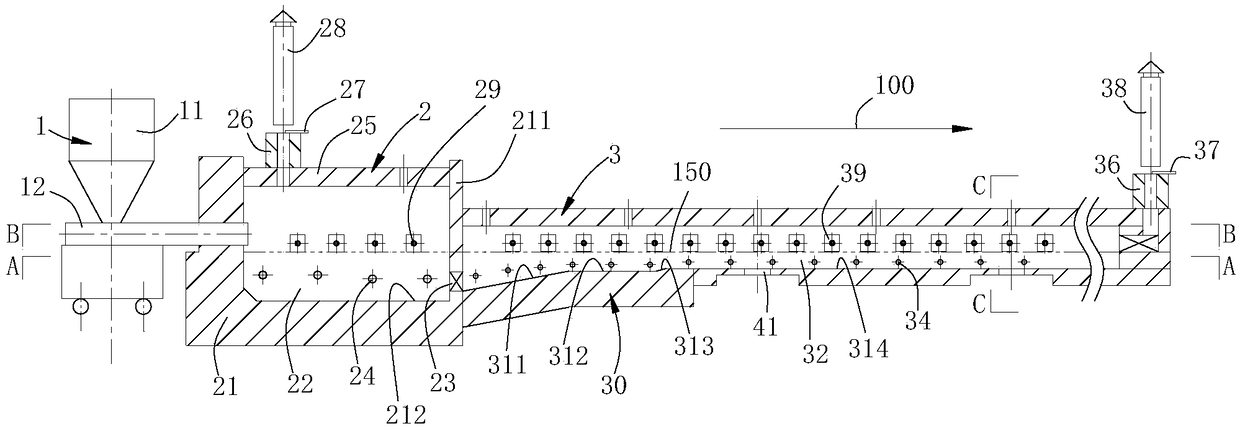
[0030] refer to Figure 1-Figure 3 , along the first direction 100, the kiln for producing basalt fiber includes a feeder 1, a melting pool 2 and a molding area 3 connected in sequence. Both the feeding machine 1 and the forming area 3 are arranged on opposite sides of the melting pool 2 .

[0031] The melting pool 2 includes a shell 21 and a melting cavity 22 arranged in the shell. The top 25 of the casing 21 is provided with a second smoke exhaust port 26, and a second chimney 28 is installed on the second smoke exhaust port 26. For the convenience of controlling the amount of smoke exhaust, a second smoke exhaust port is provided with a The second adjusting plate 27, through which the size of the second smoke outlet can be adjusted, so as to adjust the amount of smoke exhausted. A row of second electric heaters...

Embodiment 2

[0049] This embodiment is an improvement on the basis of Embodiment 1. The main difference is that the installation positions of the first flame heater and the second flame heater are different. Please refer to Figure 5 , the second flame heater 61 is vertically installed on the top 25 of the shell, the first flame heater 62 is obliquely arranged on the top 35 of the molding area 3, and the flame injection direction 300 of the first flame heater 35 is aligned with the basalt in the main channel The angle α between the flow directions 200 of the melt is 45°. It can be understood that, in other embodiments, the included angle α may also be 30°, 40°, 50°, 100° or 150°, and of course it may also be any other angle between 30°-150°.

[0050] It can be understood that on the basis of Embodiment 1, only the position of the first flame heater or the second flame heater can be adjusted. Alternatively, a first flame heater is provided on the top of the molding area and on both side wa...


PUM


Abstract

The invention discloses a kiln for producing basalt fibers. The kiln comprises a forming area extending along a first direction in the length direction, the forming area is provided with a primary material channel for circulation of basalt melt, a lug tank is arranged on one side of the width direction of the forming area and provided with a secondary material channel communicated with the primarymaterial channel, a first leakage plate is arranged at the bottom of the forming area, a second leakage plate is arranged at the bottom of the lug tank, an electric heater is arranged is arranged onthe side wall of the width direction of the forming area and arranged on the lower portion of melt setting liquid level, and a first flame heater is arranged on at least one of the top or the side wall of the width direction of the forming area and arranged on the upper portion of the melt setting liquid level. By the aid of the kiln, part of basalt melt can enter the lug tank, the length of the forming area can be effectively decreased under the condition of the same number of leakage plates, the flow distance of the basalt melt is shortened, and the quality of the basalt fibers is ensured.

Description

technical field [0001] The invention relates to a production facility of basalt fiber and belongs to the field of processing equipment for inorganic non-metallic materials. Background technique [0002] Basalt is a kind of volcanic lava with good chemical stability and thermal stability. Basalt melting is different from the batch melting process in glass production, it has no silicate reaction and purification and clarification process. The chemical composition of basalts from the same origin is relatively stable, but the composition content fluctuates. [0003] Fibers made of basalt have excellent properties such as good thermal stability, good corrosion resistance, high tensile strength, and high elastic modulus. They have been used in many fields such as shipbuilding, automobiles, aerospace, aviation, and construction, and have broad application prospects. . my country has a large amount of basalt ore reserves, and the raw material resources for producing basalt contin...

Claims


Application Information

Patent Timeline
Patent Type & Authority Applications(China)
IPC IPC(8): C03C13/06C03B37/022C03B37/08C03B37/09
CPCC03B37/022C03B37/08C03B37/09C03C13/06
Inventor 于守富李卫军谭良孙振海朱立平张建辉
Owner NANJING FIBERGLASS RES & DESIGN INST CO LTD
Why Eureka
Try Eureka