Supercharge Your Innovation With Domain-Expert AI Agents!

Over-temperature protection circuit with overcurrent protection function

An over-temperature protection circuit and over-current protection technology, applied in temperature control, non-electric variable control, instruments, etc., can solve problems such as circuit temperature threshold point and hysteresis offset

Active Publication Date: 2019-01-08
江苏芯力特电子科技有限公司
View PDF6 Cites 2 Cited by
  • Summary
  • Abstract
  • Description
  • Claims
  • Application Information

AI Technical Summary

Problems solved by technology

[0002] The over-temperature protection circuit of traditional integrated circuits such as figure 2 As shown, let the voltage across the resistor R1 be V 1 , the voltage across resistor R2 is V 2 , due to the emitter-base voltage V of transistor Q1 EB With negative temperature characteristics, at room temperature, V EB >V A , the output of the signal OTP_OUT is high level 1, so that M1 is turned on, R2 is short-circuited, and V A =V 1 , as temperature rises, V EB decreases, when V EB ≤V A , OTP_OUT flips to low level 0, and sends out a protection signal. At this time, M1 is turned off, M2 is turned on, and V A =V 1 +V 2 , the circuit is in the over-temperature protection state, as the temperature drops, V EB increase, when V EB >V A When OTP_OUT resumes outputting high level 1 again, the system works normally and can achieve the purpose of over-temperature protection, but under different supply voltages, the I PTAT Changes in the resistors R1 and R2 change the voltage, resulting in a large shift in the temperature threshold point and hysteresis of the circuit, and the circuit performance cannot be guaranteed. Moreover, the circuit needs a voltage comparator and a reference voltage, and the structure is complex. There are many components required, the circuit opening and closing is uncontrollable, the power consumption is large, and the device will be burned if the current is too high, which does not conform to the development trend of integrated circuits. The existing technology has not completely solved such problems, and the present invention achieves The purpose of the basic over-temperature protection and hysteresis is achieved, and the logic level switch is used to discharge the current, which can quickly shut down the entire circuit and reduce power consumption. When the current is too large, the circuit forms a self-locking, so that the current It reduces the power consumption, prevents the device from being burned out, protects the chip, and the self-locking circuit accelerates the inversion of the temperature detection signal output, improves the sensitivity, and the signal output circuit isolates the external signal to prevent the over-temperature detection circuit The output signal is interfered by external signals, which improves the performance of the circuit. This protection circuit provides an over-temperature protection circuit with simple structure, few components, low power consumption, high sensitivity, controllable circuit opening and closing, and self-locking over-current. High, no need for voltage comparator and reference voltage, low design difficulty, easy to adjust the over-temperature protection threshold, realize temperature hysteresis setting, etc., and also ensure the safety and service life of the chip

Method used


Image

  • Over-temperature protection circuit with overcurrent protection function
  • Over-temperature protection circuit with overcurrent protection function
  • Over-temperature protection circuit with overcurrent protection function

Examples


Embodiment Construction

[0019] The present invention will be further described below with reference to the accompanying drawings. The following embodiments are only used to illustrate the technical solutions of the present invention more clearly, and cannot be used to limit the protection scope of the present invention.

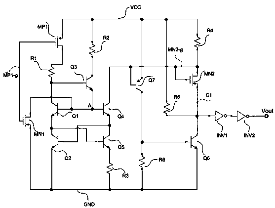
[0020] Such as figure 1 As shown, an over-temperature protection circuit with over-current protection includes: a power supply VCC, a first PMOS tube MP1, a first NMOS tube MN1, a second NMOS tube MN2, a first bipolar transistor Q1, a second double Polar transistor Q2, third bipolar transistor Q3, fourth bipolar transistor Q4, fifth bipolar transistor Q5, sixth bipolar transistor Q6, seventh bipolar transistor Q7, first resistor R1, Second resistor R2, third resistor R3, fourth resistor R4, fifth resistor R5, sixth resistor R6, first inverter INV1, second inverter INV2;

[0021] The drain terminal of the first PMOS tube MP1 is connected to one end of the first resistor R1; the gate of ...


PUM


Abstract

The invention discloses an over-temperature protection circuit with an overcurrent protection function. The over-temperature protection circuit comprises a power supply VCC, a first PMOS transistor MP1, a first NMOS transistor MN1, a second NMOS transistor MN2, a first bipolar transistor Q1, a second bipolar transistor Q2, a third bipolar transistor Q3, a fourth bipolar transistor Q4, a fifth bipolar transistor Q5, a sixth bipolar transistor Q6, a seventh bipolar transistor Q7, a first resistor R1 a second resistor R2, a third resistor R3, a fourth resistor R4, a fifth resistor R5, a sixth resistor R6, a first inverter INV1, and a second inverter INV2. The output of an over-temperature detection circuit of the over-temperature protection circuit disclosed by the invention is a detection signal of temperature change; in a temperature rise process, when the temperature exceeds an over-temperature threshold TH, the detection signal output changes from a high level to a low level, and theprotection circuit is activated to generate an over-temperature protection signal; and in a temperature drop process, when the temperature is lower than a recovery threshold TL, the detection signal output changes from the low level to the high level, the protection circuit is turned off, and the chip recovers the normal work.

Description

Technical field [0001] The invention relates to the field of integrated circuits, in particular to an over-temperature protection circuit. Background technique [0002] The over-temperature protection circuit of traditional integrated circuit such as figure 2 As shown, suppose the voltage across resistor R1 is V 1 , The voltage across resistor R2 is V 2 , Because the emitter-base voltage of transistor Q1 is V EB Has negative temperature characteristics, at room temperature, V EB > V A When the output of the signal OTP_OUT is high level 1, M1 is turned on, R2 is short-circuited, and V A =V 1 , As the temperature rises, V EB Decrease, when V EB ≤V A When, OTP_OUT flips to low level 0 and sends out a protection signal. At this time, Ml is turned off, M2 is turned on, and V A =V 1 +V 2 , The circuit is in the over-temperature protection state, as the temperature drops, V EB Increase, when V EB > V A When OTP_OUT returns to output high level 1, the system works normally and ...

Claims


Application Information

Patent Timeline
IPC IPC(8): G05D23/20
CPCG05D23/20
Inventor 金湘亮李晓张文杰
Owner 江苏芯力特电子科技有限公司
Features
  • R&D
  • Intellectual Property
  • Life Sciences
  • Materials
  • Tech Scout
  • Unparalleled Data Quality
  • Higher Quality Content
  • 60% Fewer Hallucinations
Learn More