
A groove-type anode fast recovery diode with bipolar Schottky control and a manufacturing method thereof

A recovery diode, groove type technology, used in diodes, semiconductor/solid-state device manufacturing, electrical components, etc., can solve the problem of excessively high oscillating current and voltage, long reverse recovery time, increasing system circuit power consumption and limiting system operating frequency and other problems, to achieve the effect of easy passage and reduction of reverse recovery time

Active Publication Date: 2019-01-11
SOUTHEAST UNIV +1
View PDF4 Cites 12 Cited by
  • Summary
  • Abstract
  • Description
  • Claims
  • Application Information

AI Technical Summary

Problems solved by technology

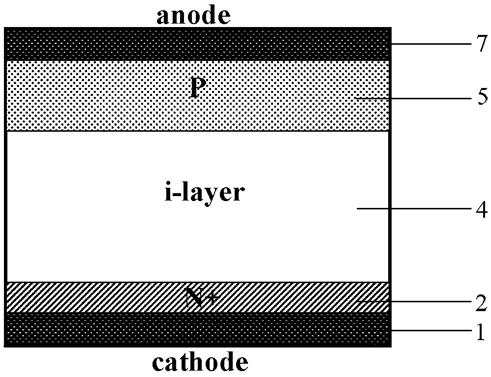
It is also because of this that the traditional PiN diode has a large amount of minority carriers stored in the intrinsic region during the forward conduction period, so that during the reverse recovery period, the extraction speed of the minority carriers in the intrinsic region is slow, and finally It leads to a longer reverse recovery time, which seriously increases the power consumption of the system circuit and limits the improvement of the system operating frequency.
In order to improve the switching speed of FRD, lifetime control technology is often used, such as metal impurity doping and electron irradiation technology to reduce the lifetime of minority carriers in the intrinsic region. Using this technology can effectively shorten the reverse recovery of FRD time, increase the switching speed, but at the same time, it will also cause a high reverse leakage current, which seriously affects the normal logic function of the circuit system. The oscillating current and voltage will seriously threaten the reliability of the device

Method used


Image

  • A groove-type anode fast recovery diode with bipolar Schottky control and a manufacturing method thereof
  • A groove-type anode fast recovery diode with bipolar Schottky control and a manufacturing method thereof
  • A groove-type anode fast recovery diode with bipolar Schottky control and a manufacturing method thereof

Examples


Embodiment Construction

[0035] Below in conjunction with accompanying drawing, the present invention is described in detail:

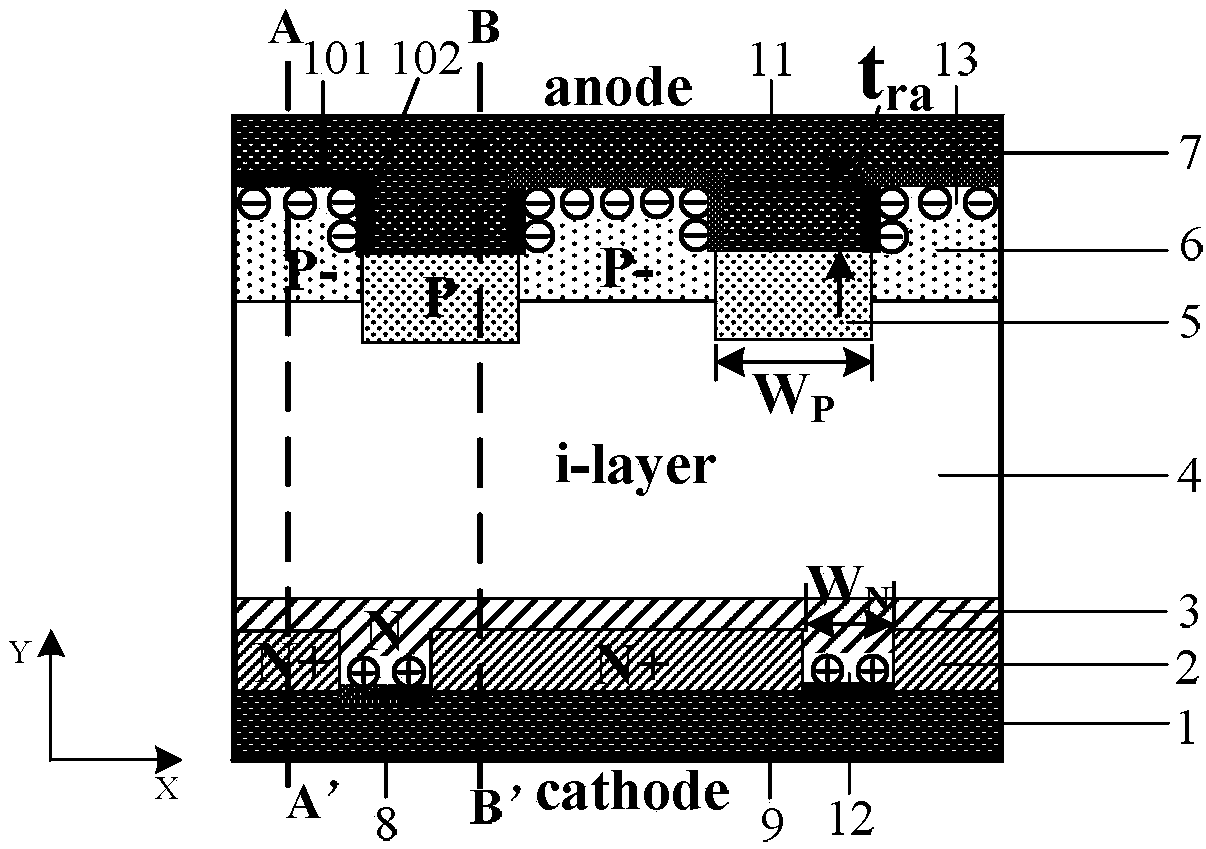
[0036] A notched anode fast recovery diode with bipolar Schottky control such as figure 2 As shown, it includes: a cathode metal 1 with an N-type intrinsic region 4 above the cathode metal 1 and an anode metal 7 above the N-type intrinsic region 4. It is characterized in that a lightly doped The hetero-doped N-type region 3 and the heavily doped N-type region 2, the lightly doped N-type region 3 and the heavily doped N-type region 2 are arranged at intervals, the bottom of the lightly doped N-type region 3 is connected to the cathode metal 1 It is a Schottky contact 8, and the lightly doped N-type region 3 extends toward the N-type intrinsic region 4 and makes the heavily doped N-type region 2 covered by the extension of the lightly doped N-type region 3 , the N-type intrinsic region 4 is located on the upper surface of the extension of the lightly doped N-type region 3; be...


PUM


Abstract

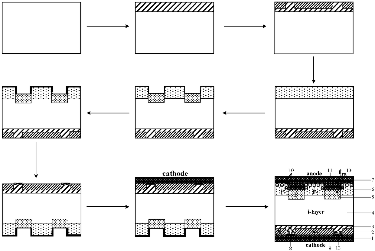
The invention relates to a groove-type anode fast recovery diode with bipolar Schottky control and a manufacturing method thereof. The diode includes a cathode metal, Above the cathode metal there isan N-type intrinsic region, Above the N-type intrinsic region there is an anode metal, the cathode metal is provided with a lightly doped N-type region and a heavily doped N-type region spaced apart from each other, the bottom of the lightly doped N-type region is in Schottky contact with the cathode metal, A heavily doped P-type region and a lightly doped P-type region are arranged between the N-type intrinsic region and the anode metal, and the upper surface of the heavily doped P-type region is lower than the upper surface of the lightly doped P-type region, so that a groove-type anode region is formed, and the lightly doped P-type region is in Schottky contact with the anode metal. The manufacturing method of the groove-type anode fast recovery diode with bipolar Schottky control is characterized in that Schottky contacts of an anode surface and a sidewall can be simultaneously formed by one-step etching.

Description

technical field [0001] The invention mainly relates to the technical field of power semiconductor devices, in particular to a groove type anode fast recovery diode with bipolar Schottky control. Background technique [0002] In various frequency conversion circuits and power electronic systems, whether the main circuit in the circuit is a thyristor with commutation shutdown or a new type of switching device with self-shutoff capability, it is necessary to connect it in parallel and provide freewheeling. The diode of the loop (subsequently referred to as FRD). As the frequency and performance of power electronic devices in these circuit systems continue to increase, in order to match their turn-off capabilities, their FRDs must have fast turn-on and turn-off capabilities, that is, have a lower forward conduction voltage V F and extremely short reverse recovery time. At the same time, in order to improve the energy efficiency and reliability of the system, its FRD must have ...

Claims


Application Information

Patent Timeline
IPC IPC(8): H01L29/872H01L29/06H01L21/329
CPCH01L29/0615H01L29/66143H01L29/66212H01L29/872
Inventor 祝靖李少红孙玲张龙孙伟锋陆生礼时龙兴
Owner SOUTHEAST UNIV
Learn More