A granulation device and heat recovery method for molten slag

A slag granulation and molten slag technology, applied in recycling technology and other directions, can solve the problems of energy-saving economy, large air volume, large air pressure, low air density and impact force, etc.

Active Publication Date: 2020-02-14
TIANJIN UNIV
View PDF5 Cites 0 Cited by
  • Summary
  • Abstract
  • Description
  • Claims
  • Application Information

AI Technical Summary

Problems solved by technology

Due to the low density and low impact force of the air, the air volume and air pressure required to granulate molten slag are large, which will inevitably lead to problems such as large power consumption of the air source and low temperature of the recovered heat exchange air, which is difficult to meet the energy-saving and economical requirements.

Method used


Image

  • A granulation device and heat recovery method for molten slag
  • A granulation device and heat recovery method for molten slag
  • A granulation device and heat recovery method for molten slag

Examples


Embodiment 1

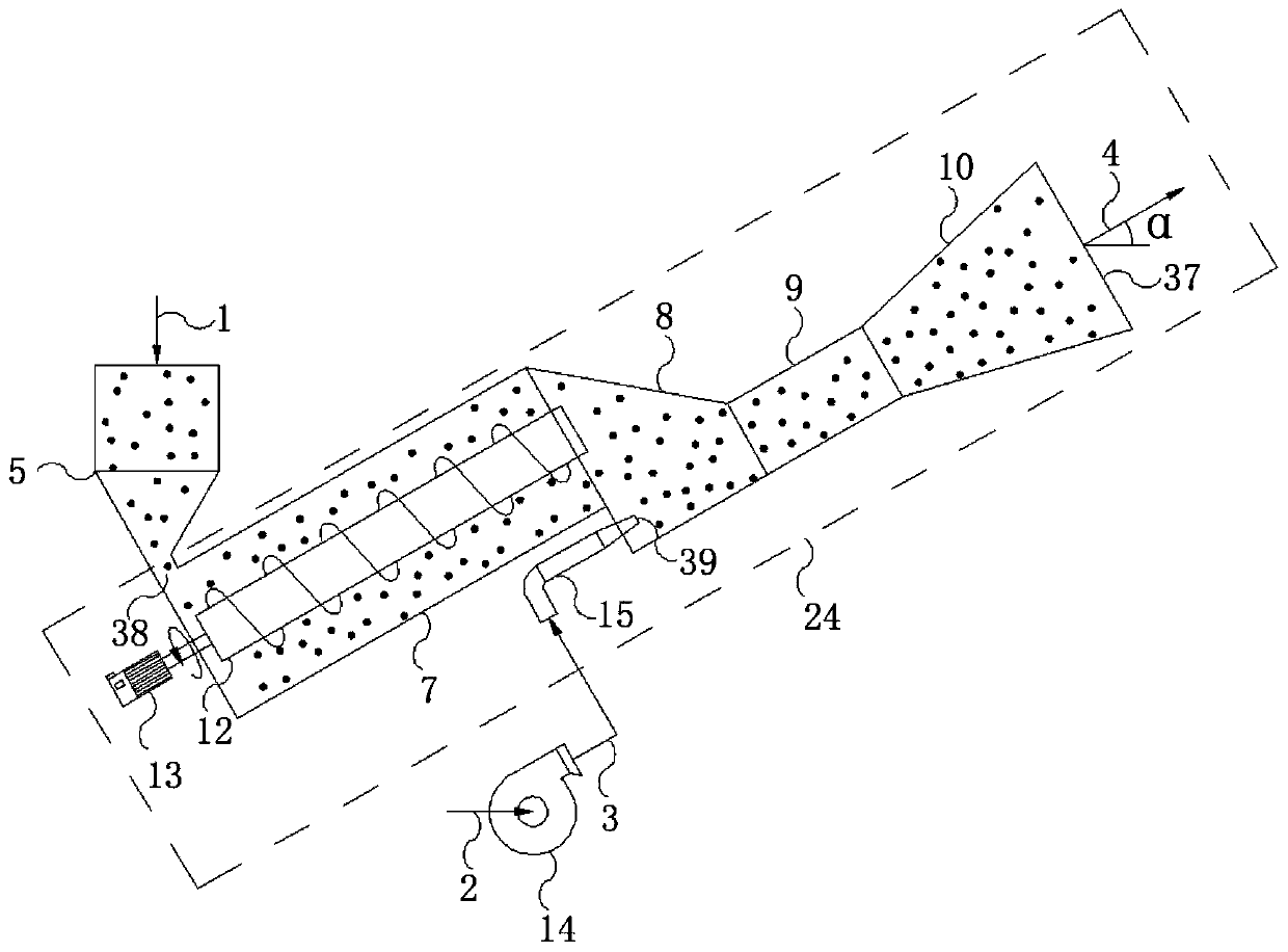
[0051] This embodiment is a molten slag granulation device and a heat recovery method, including three processes of gas powder flow generation, molten slag granulation, and powder return. The gas powder flow generation process is as follows figure 1 As shown, it is produced by a low-pressure screw pump air-transporting powder flow mixer, and the mixer is provided with a feeding section 7, an accelerating section 8, a mixing section 9, and an injection section 10. The mass ratio of powder to air is 70:1. After the powder 1 enters the powder inlet 38 from the hopper 5, the screw shaft 12 with blades is driven by the motor 13 to make the powder flow from the feeding section 7 continuously. Pressed to the acceleration section 8, the compressed air 3 generated by the airflow power provided by the high-pressure fan or blower 14 enters the acceleration section 8 of the gas-powder mixer from the gas inlet 39, and the gas-powder mixture completes powder acceleration and forms in the ac...

Embodiment 2

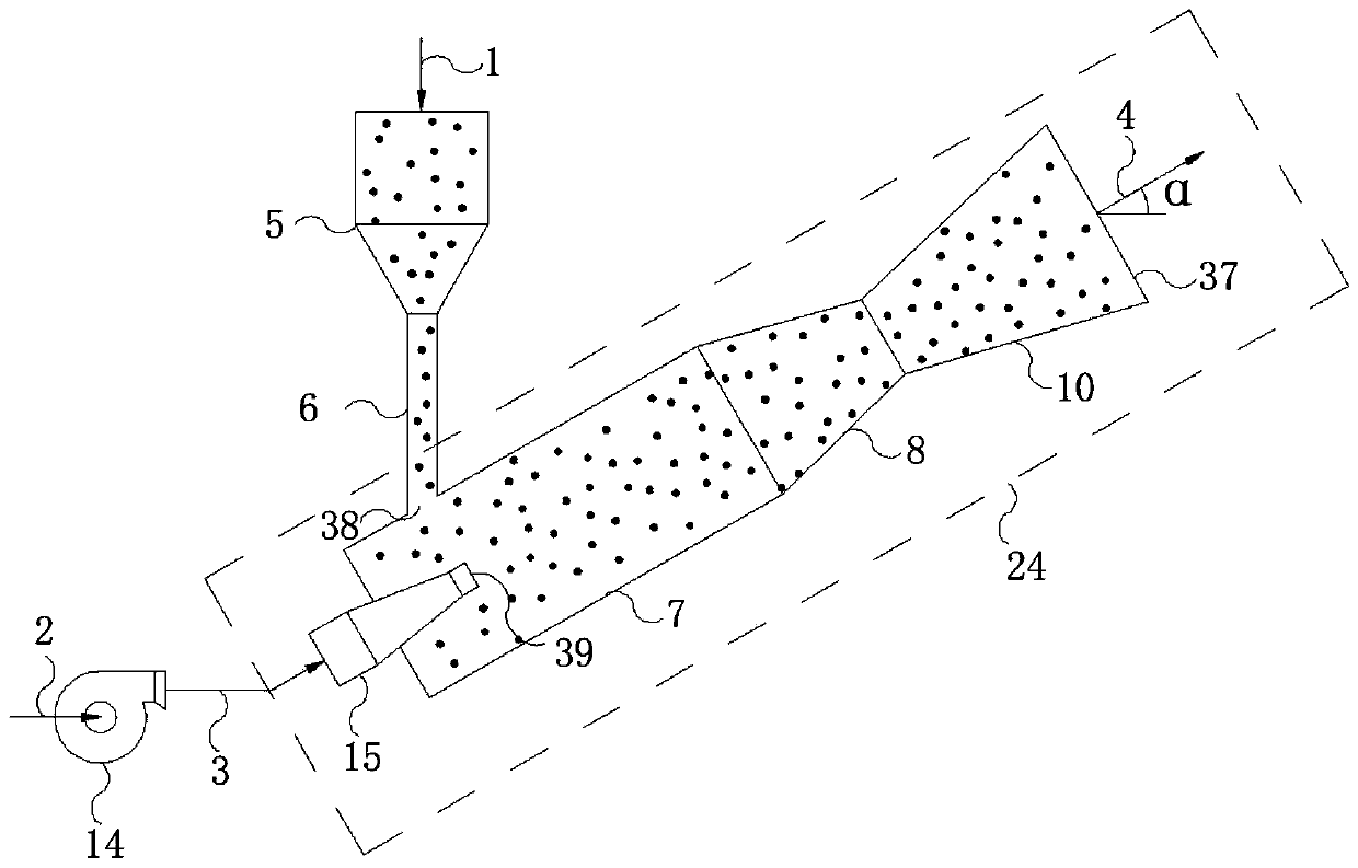
[0054] This embodiment is a molten slag granulation device and a heat recovery method, including three processes of gas powder flow generation, molten slag granulation, and powder return. The gas powder flow generation process is as follows figure 2 As shown, it is produced by a low-pressure gravity flow gas-conveying powder flow mixer, and a feeding section 7, an accelerating section 8, and an injection section 10 are arranged in the mixer. The mass ratio of powder to air is 90:1. The installation height of the powder feed hopper 5 is much higher than that of the air-powder mixer. The powder 1 falls into the air powder from the powder inlet 38 through the vertical feeding section 6 by its own gravity. The conveying section 7 of the mixer uses the compressed air 3 produced by the high-pressure fan or blower 13 as the working medium to enter the conveying section 7 from the gas inlet 39 to mix with the powder, and the air-powder flow mixture completes the powder acceleration i...

Embodiment 3

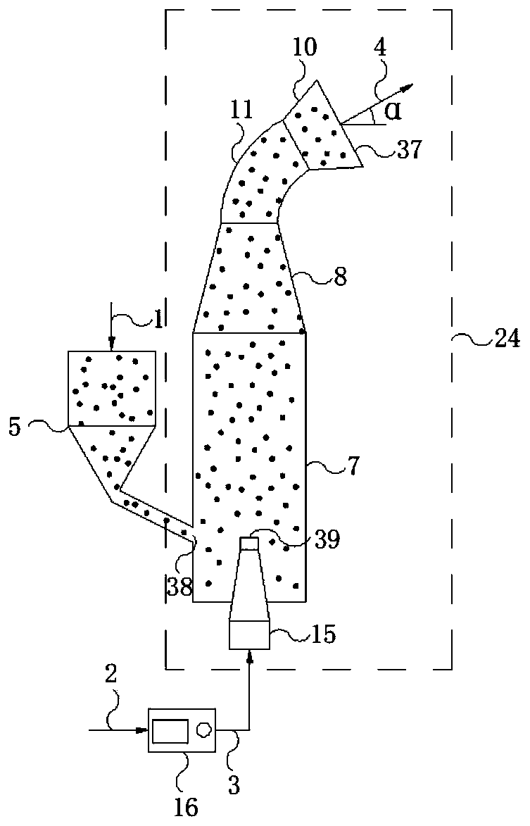
[0057] This embodiment is a molten slag granulation device and a heat recovery method, including three processes of gas powder flow generation, molten slag granulation, and powder return. The gas powder flow generation process is as follows image 3 As shown, it is produced by a high-pressure air compressor gas delivery powder mixer. The mixer is provided with a feeding section 7, a curved flow path 11, and an injection section 10. The arc of the curved pipeline is 60°. The mass ratio of powder to air is 110:1. The compressed air 3 produced by the air compressor 16 is used as the working medium to enter the delivery section 7 of the jet powder mixer from the gas inlet 39, and the hopper is fed by airflow suction. The powder in 5 is sucked into the air-powder mixer, and the air-powder flow mixture completes the powder acceleration in the acceleration section 8, and the large particle powder is sprayed out close to the outside of the elbow under the action of centrifugal force i...


PUM

PropertyMeasurementUnit
thicknessaaaaaaaaaa

Abstract

The invention relates to a granulating device and heat recovery method for melted slag. The heat recovery method comprises the following procedures: an air-powder flow production procedure: mixing powder with compressed air; a melted slag granulation procedure: jetting the produced air-powder flow to a melted slag flow to convert the melted slag flow into high-temperature granulated slag; and a melted slag powder returning procedure: returning fine-grain powder produced in the melted slag granulation procedure as powder for the air-powder flow production procedure to the air-powder flow production procedure for cyclic usage. According to the invention, high-speed air-powder flow is used as a granulating medium for granulation of the melted slag into high-temperature melted particles; fineslag particles obtained after screening of cooled granulated slag are used as the powder for the air-powder flow for cyclic usage; and waste heat in high-temperature granulation air after granulationof the melted slag is utilized. During granulation and heat recovery of a melting furnace, the energy loss of the granulating medium is low; impact kinetic energy on the melted slag is large; and on the premise of ensuring the granulation effect of the melted slag, the energy consumption of an air source can be reduced and high-grade hot air can be obtained.

Description

technical field [0001] The invention relates to a granulation device and a heat recovery method for molten slag, especially relying on the fine powder in the gas powder flow to blow off the molten slag, which can reduce the power attenuation in the process of air jet injection, reduce energy loss, and reduce The granulated air flow rate is used to obtain high-grade hot air, and the vitreous rate of granulated slag is guaranteed to be used in the production of high value-added products. It belongs to the field of molten slag recycling, waste heat recovery and environmental protection. Background technique [0002] Molten slag refers to the molten metallurgical slag discharged from the smelting furnace during the production process of the metallurgical industry, including blast furnace slag and steel slag produced in the ironmaking furnace, copper slag, lead slag, zinc slag, nickel slag produced in non-ferrous metal smelting slag and other non-ferrous metal slag, red mud disch...

Claims


Application Information

Patent Timeline
Patent Type & Authority Patents(China)
IPC IPC(8): C21B3/08C21B3/06
CPCC21B3/06C21B3/08Y02W30/50
Inventor 张书廷刘栩雯
Owner TIANJIN UNIV
Why Eureka
Try Eureka