Test method and device for rear beam splitting pupil laser differential confocal Brillouin-Raman spectrum

A technology of spectral testing and differential confocal, which is applied in measuring devices, analytical materials, scattering characteristics measurement, etc., can solve problems such as low spatial resolution and large limitations, and improve the spectral signal-to-noise ratio of the system and improve the system The effect of lateral resolution

Inactive Publication Date: 2019-01-15
BEIJING INSTITUTE OF TECHNOLOGYGY
View PDF7 Cites 5 Cited by
  • Summary
  • Abstract
  • Description
  • Claims
  • Application Information

AI Technical Summary

Problems solved by technology

[0012] The purpose of the present invention is to solve the problem that the existing technology is limited by external factors and the s

Method used


Image

  • Test method and device for rear beam splitting pupil laser differential confocal Brillouin-Raman spectrum
  • Test method and device for rear beam splitting pupil laser differential confocal Brillouin-Raman spectrum
  • Test method and device for rear beam splitting pupil laser differential confocal Brillouin-Raman spectrum

Examples


Embodiment 1

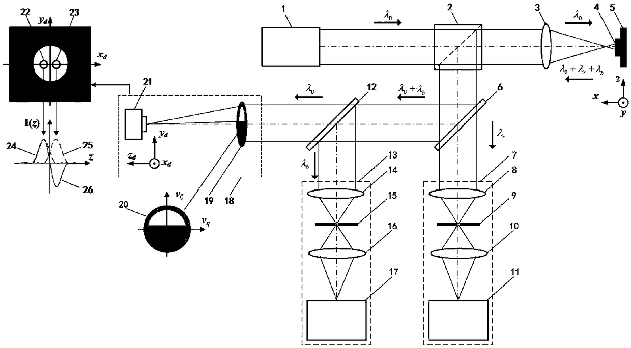
[0051] like image 3 As shown, a collection pupil 20 is placed on the pupil plane of the collection objective 19. The excitation beam emitted by the light source system 1 passes through the beam splitter prism 2 and the measurement objective lens 3, and then converges on the measured sample 4 to excite the Raman scattered light and Brillouin scattered light carrying the characteristic parameter information of the sample micro-area, and reflect at the same time. Rayleigh scattered light. Raman scattered light, Brillouin and Rayleigh scattered light are collected by the measuring objective lens, and after being reflected by the beam splitting prism 2, they are divided into two beams by the dichroic spectroscopic system 6, and the Rayleigh scattering light reflected by the dichroic spectroscopic system 6 The light and the Brillouin scattered light enter the spectroscopic system 12 , the Rayleigh scattered light and the Brillouin scattered light reflected by the spectroscopic sys...

Embodiment 2

[0060] In this embodiment, the light source system 1 adopts a 532 nm continuous laser, the dichroic spectroscopic system 6 adopts NotchFilter, the Raman spectrum detection unit 11 adopts a Raman spectrometer, and the Brillouin spectrum detection unit 17 adopts a Brillouin spectrometer.

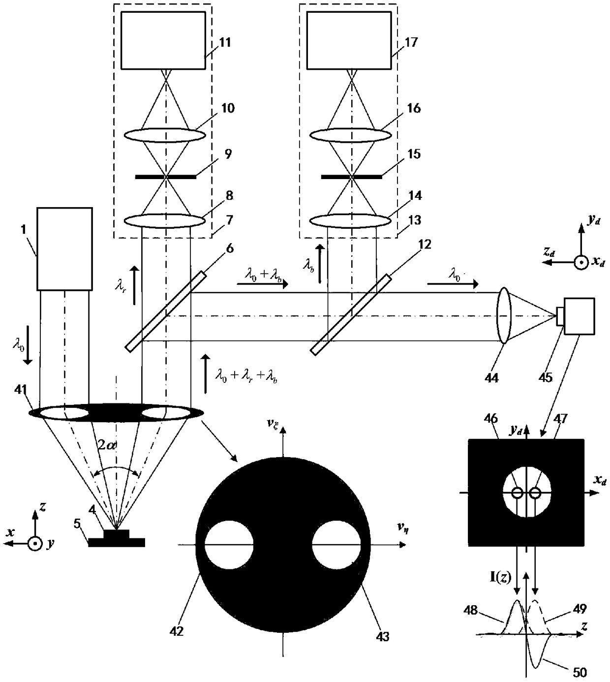
[0061] like Figure 11 As shown, the post-pupil laser differential confocal Brillouin-Raman spectral detection process is as follows:

[0062]First, the laser light emitted from the light source system 1 formed by the laser is condensed by the fifth condensing mirror 30 into the third pinhole 31 , and then collimated and expanded by the sixth condensing mirror 32 to form a parallel excitation beam. After the excitation beam passes through the radial polarization conversion system 27 , the beam splitter prism 2 and the pupil filter 28 , the measured objective lens 3 converges on the measured sample 4 to excite the Raman scattered light carrying the micro-area characteristic parameters of the me...


PUM


Abstract

The invention relates to a test method and device for a rear beam splitting pupil laser differential confocal Brillouin Raman spectrum, and belongs to the technical field of microscopic spectral imaging. Constructing a beam splitting pupil differential confocal microscopic imaging system through the Rayleigh scattered light which is abandoned in the confocal Raman spectrum detection system, and realizing the high spatial resolution detection of the sample geometry; obtaining the various basic properties of the detected sample by detecting the abandoned Brillouin scattered light in the confocalRaman spectrum detection system, so that measuring parameters such as elasticity, density, and elasticity of the material; acquiring the spectral information at the focal point of the sample accurately by using the focal position obtained by the beam splitting pupil laser differential confocal microscopic imaging system, so that realizing the optical splitting pupil differential confocal Brillouin-Raman spectrum high spatial resolution imaging and detection of an atlas; realizing the multi-parameter comprehensive measurement of the morphology performance of the sample by fusing the confocal Raman spectrum detection technology with the confocal Brillouin spectrum detection technology.

Description

technical field [0001] The invention relates to a post-pupil laser differential confocal Brillouin-Raman spectrum testing method and device, and belongs to the technical field of microscopic spectrum imaging. The post-pupil laser differential confocal microscopy technology, Raman spectroscopy detection technology and Brillouin spectroscopy detection technology are organically combined, and a post-pupil laser differential confocal Brillouin-Raman spectroscopy is involved. Mann spectroscopy testing method and device can be used for high spatial resolution detection of various parameters of micro-region mechanical morphological properties of various samples, etc. Background technique [0002] Scattering effects occur when photons interact with phonons in matter. Scattering where the frequency does not change is called elastic scattering (Rayleigh scattering), and scattering where the frequency changes is called inelastic scattering (Raman scattering and Brillouin scattering). ...

Claims


Application Information

Patent Timeline
IPC IPC(8): G01N21/65G01N21/47G01N21/01
Inventor 赵维谦吴寒旭邱丽荣王允
Owner BEIJING INSTITUTE OF TECHNOLOGYGY
Why Eureka
Try Eureka