Portable micro-fluidic chip, detection device and micro-fluidic detection method

A microfluidic chip, portable technology, applied in the field of medical testing, can solve the problem of being unable to be used portablely

Inactive Publication Date: 2019-01-18
首慈康健养老集团有限公司
View PDF4 Cites 8 Cited by
  • Summary
  • Abstract
  • Description
  • Claims
  • Application Information

AI Technical Summary

Problems solved by technology

[0006] In view of this, the present invention discloses a portable microfluidic chip, which effectively solves the technical defect that the current microfluidic chip detection technology still cannot be used portablely

Method used


Image

  • Portable micro-fluidic chip, detection device and micro-fluidic detection method
  • Portable micro-fluidic chip, detection device and micro-fluidic detection method
  • Portable micro-fluidic chip, detection device and micro-fluidic detection method

Examples


Embodiment 1

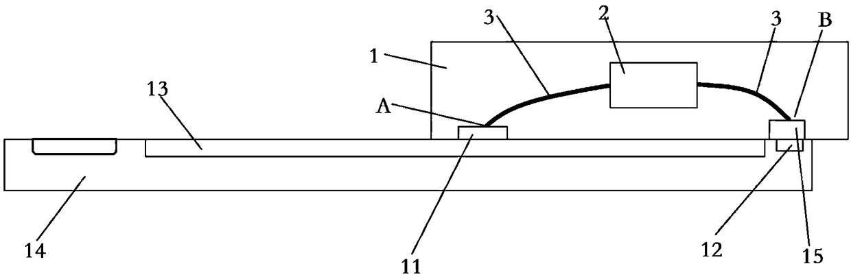
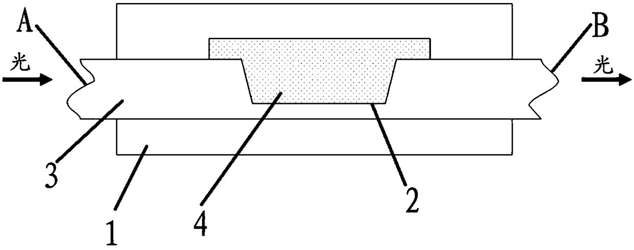
[0069] see Figure 1 to Figure 5, the microfluidic chip of this embodiment includes a microfluidic opaque chip substrate 1, a test object detection chamber 4, a side-polished optical fiber 3, a light-transmitting area 11 and a detection area 15; the side-polished optical fiber 3 is fixed It is arranged on the surface of the microfluidic opaque chip substrate 1, and the opening of the side polishing area 2 of the side polished optical fiber is arranged upwardly on the surface of the microfluidic opaque chip substrate 1; On the microfluidic opaque chip substrate 1 corresponding to the position of the input end A of the polished optical fiber, the light-transmitting area 11 enables the light source to be transmitted to the input end A of the side polished optical fiber; The position of the output end B of the optical fiber corresponds to the microfluidic opaque chip substrate 1, wherein the detection area 15 enables the light source to be transmitted to the output end B of the si...

Embodiment 2

[0088] In this embodiment, the test substance is randomly prepared NaCl solution, the negative control sample is pure water, and the positive control sample is NaCl solution of known concentration.

[0089] Table 1 uses different concentrations of NaCl solutions to make a standard curve

[0090]

[0091] The ratio of the light intensity of the input end of the side-polished optical fiber and the output end of the side-polished optical fiber of the microfluidic chip disclosed in the present invention is converted into a concentration value according to the standard curve, which lies in the concentration ratio of the analyte measured by the spectrophotometer Yes, the experiment was repeated 3 times, and the test results are shown in Table 1-Table 2 and Figure 5 shown.

[0092] Table 2 The detection results of the randomly prepared NaCl solution measured by the microfluidic chip and spectrophotometry

[0093]

[0094] Conclusion: The measurement results of the microfluid...

Embodiment 3

[0096] In this embodiment, a quality control genome sample (0.01 g / L) was used as a positive control sample, a negative control sample was pure water, and the test substance was cellular genomic DNA extracted from 5 million human-derived HBE cells.

[0097] see Figure 9 1 μl each of the negative sample, the positive sample, and the analyte are respectively added to the side polishing area 2 of the analyte detection chamber 4 through the sample delivery channel 9, and the light-emitting component is emitted at the input end of the side polishing optical fiber of the microfluidic chip. The light source is a light source with an absorption wavelength of 260nm, and a standard curve is drawn by the light intensity at the input end of the side-polished optical fiber and the light intensity at the output end of the side-polished optical fiber. The negative control sample is detected first, and the concentration value of the negative control sample is displayed on the liquid crystal ...


PUM


Abstract

The invention belongs to the technical field of medical detection and especially relates to a portable micro-fluidic chip, a detection device and a micro-fluidic detection method. The portable micro-fluidic chip provided by the invention comprises a micro-fluidic chip substrate, a to-be-detected article detection chamber and a lateral polishing optical fiber; the lateral polishing optical fiber isfixedly arranged on the surface of the micro-fluidic chip substrate; a lateral polishing area of the lateral polishing optical fiber is arranged on the surface of the micro-fluidic chip substrate inthe manner of opening being upward; the to-be-detected article detection chamber is wrapped on the periphery of the lateral polishing area of the lateral polishing optical fiber, so that the to-be-detected article is placed in the lateral polishing area of the to-be-detected article detection chamber. The invention also discloses a portable micro-fluidic detection device and the micro-fluidic detection method. The invention can solve the technical defects of low detection sensitivity and accuracy of the traditional micro-fluidic chip and oversize of the micro-fluidic detection device.

Description

technical field [0001] The invention belongs to the technical field of medical detection, and in particular relates to a portable microfluidic chip, a detection device and a microfluidic detection method. This application claims the rights and interests of the Chinese patent (patent application number 201820190178.0) submitted on February 05, 2018, and the entire content of the above application is hereby incorporated herein by reference. Background technique [0002] In the fields of chemistry, biology and medicine, it is often necessary to analyze the content of the material components in the solution. The spectrophotometer is a commonly used instrument and equipment for determining the content of the material components in the solution. It has a wide range of applications in the fields of chemistry, environmental science, biology and medicine. Applications. A spectrophotometer is mainly composed of a light source, a monochromator, a sample chamber, a detector, a signal p...

Claims


Application Information

Patent Timeline
Patent Type & Authority Applications(China)
IPC IPC(8): B01L3/00G01N21/01G01N21/17G01N21/84
CPCB01L3/5027B01L3/502707B01L2200/027B01L2200/10B01L2300/12G01N21/01G01N21/17G01N21/84G01N2021/0112
Inventor 陈龙陈哲
Owner 首慈康健养老集团有限公司
Why Eureka
Try Eureka