A method for manufacturing an electromagnetic shielding optical window by using electric field driven jet 3D printing

A 3D printing and electromagnetic shielding technology, which is applied in the fields of magnetic/electric field shielding, additive manufacturing, electrical components, etc., can solve the problem of inability to achieve high-viscosity and high-silver-content nano-silver paste printing, limited viscosity of printing materials, and difficulty in large-area manufacturing, etc. problems, to achieve excellent electromagnetic shielding efficiency, super electromagnetic shielding performance, and low manufacturing cost

Active Publication Date: 2019-01-18
QINGDAO TECHNOLOGICAL UNIVERSITY
View PDF8 Cites 3 Cited by
  • Summary
  • Abstract
  • Description
  • Claims
  • Application Information

AI Technical Summary

Problems solved by technology

[0008] At present, there are many manufacturing methods based on the metal grid structure electromagnetic shielding optical window metal grid, such as optical lithography, nanoimprinting, inkjet printing, aerosol printing, electrohydrodynamic jet printing and other manufacturing technologies, but these technology or solution currently has certain limitations
(1) Optical lithography: Traditional photolithography is a commonly used method for preparing metal grid transparent electrodes, which can realize large-scale large-scale preparation and mature technology, but it requires very high flatness of the substrate, which is difficult To achieve large-area manufacturing, the manufacturing cost is very high; (2) nanoimprinting method can achieve ultra-high resolution (minimum to 200nm) and can achieve a large aspect ratio, but nanoimprinting faces severe challenges in large-scale manufacturing Challenges. In large-area manufacturing, the large contact area between the template and the imprinted pattern will cause problems such as difficult peeling and deformation of the imprinted pattern. At the same time, the preparation of high-precision templates usually requires electron beam etching or focused ion beam etching. Time-consuming and expensive; (3) Inkjet printing (whether it is thermal bubble or piezoelectric) is currently facing the problem of low resolution (line width greater than 20 μm), which cannot meet the needs of transparent electrodes in many fields such as touch screens and OLEDs. Requirements, an...

Method used


Image

  • A method for manufacturing an electromagnetic shielding optical window by using electric field driven jet 3D printing
  • A method for manufacturing an electromagnetic shielding optical window by using electric field driven jet 3D printing
  • A method for manufacturing an electromagnetic shielding optical window by using electric field driven jet 3D printing

Examples


Embodiment 1

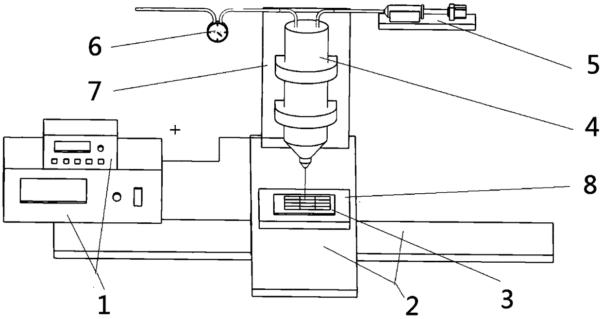
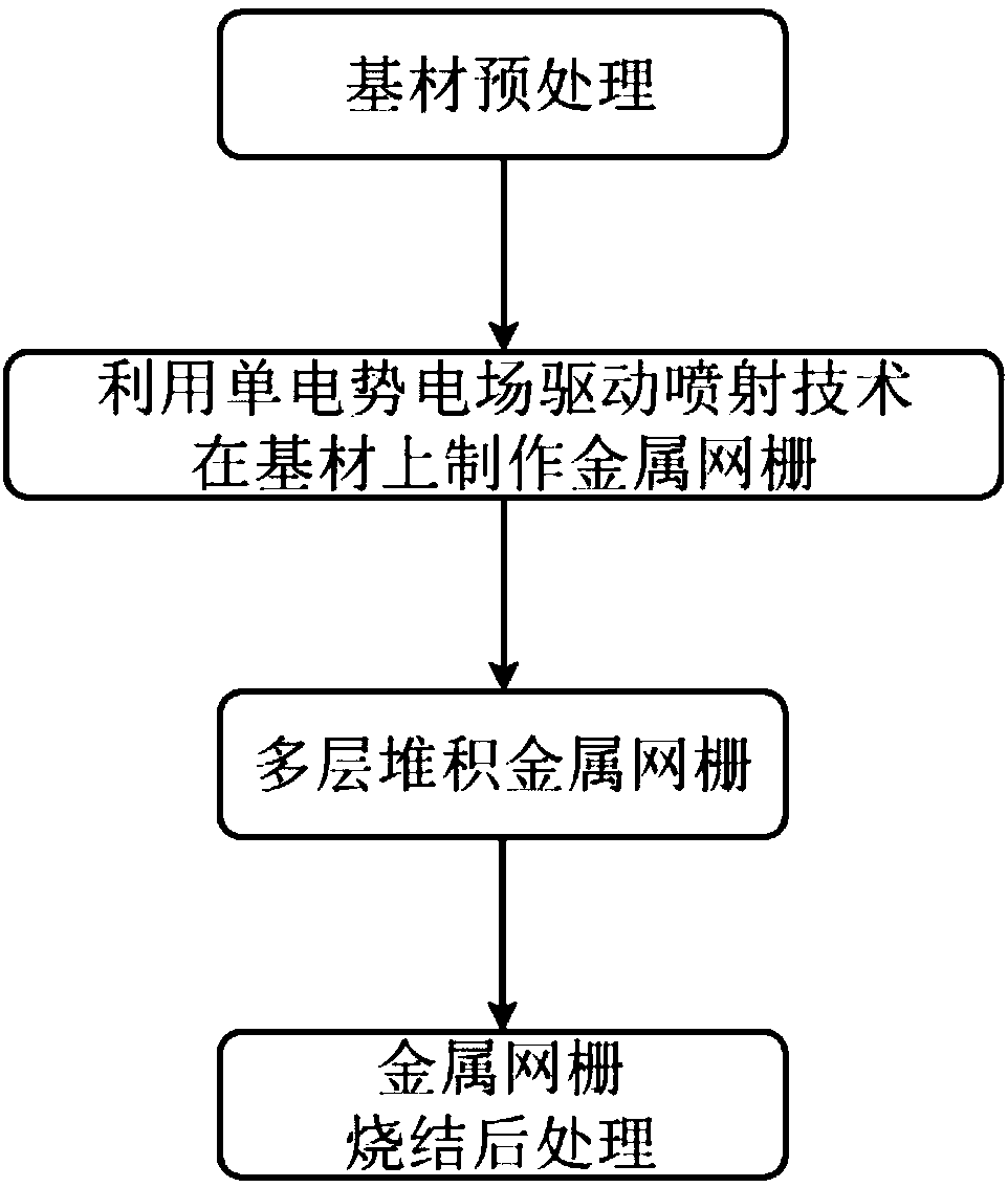
[0060] In this embodiment, the glass of 200x200mm is used as the base material, the particle-free nano-silver paste is used as the printing material (the silver content exceeds 20%), and the glass needle is used as the nozzle, and the production cycle of the 3D printer driven by electric field is 100 microns. A metal grid with a width of 2 microns and an aspect ratio of 2:1, the working principle of the electric field-driven jet deposition 3D printer is as follows figure 1 As shown, the manufacturing process of metal grid electromagnetic shielding optical window is as follows figure 2 As shown, the specific steps include:

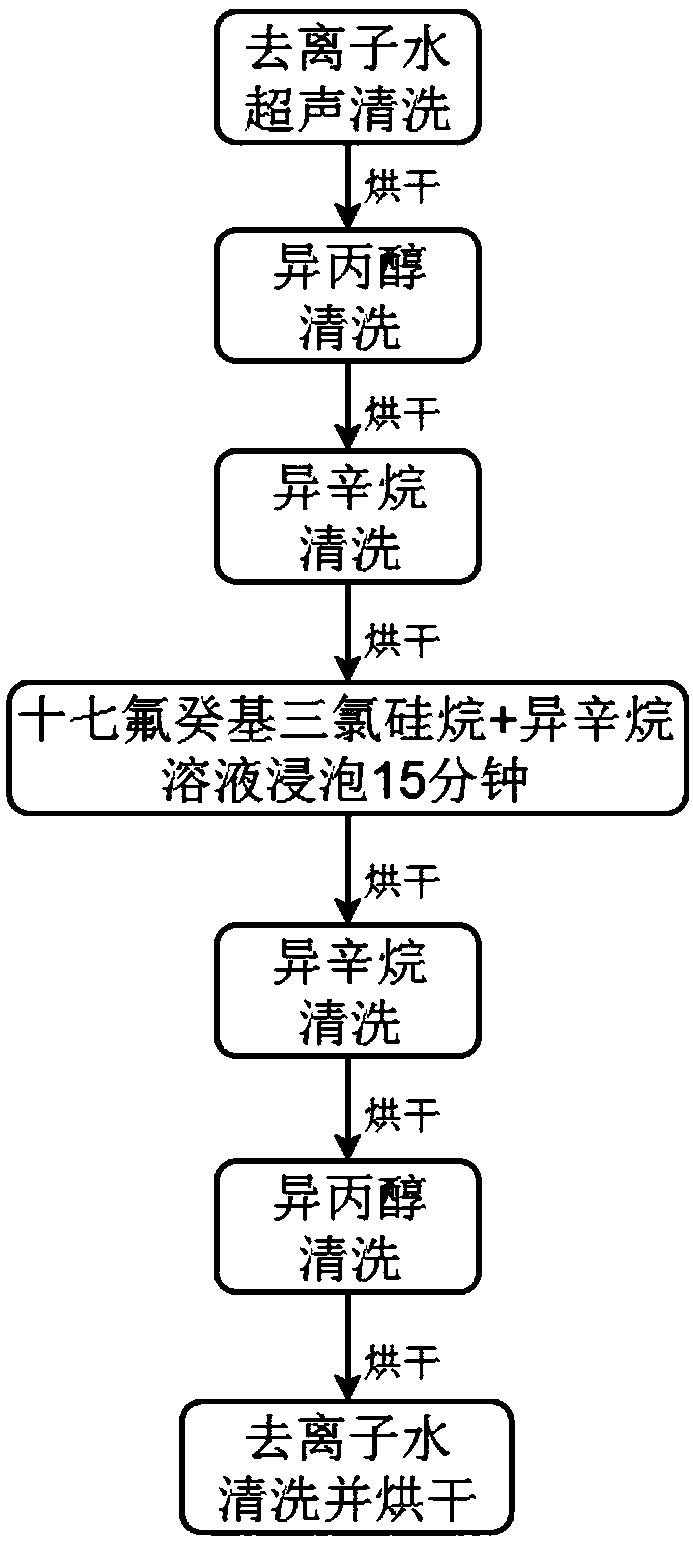
[0061] Step 1: Substrate pretreatment. according to image 3 The process is to pretreat the glass substrate, including: deionized water ultrasonic cleaning, isopropanol cleaning, isooctane cleaning, heptadecafluorodecyltrichlorosilane + isooctane solution soaking for 15 minutes, isooctane cleaning , isopropanol cleaning, deionized water cleaning and dry...

Embodiment 2

[0065] In this example, 300x300mm glass is used as the base material, the glass needle is used as the nozzle, and nano-particle silver paste is used as the printing material. The production cycle of the 3D printer is 150 microns, the line width is 3 microns, and the aspect ratio is 1:1. The metal grid, the specific steps include:

[0066] Step 1: Substrate pretreatment. Pretreatment of the glass substrate, including: deionized water ultrasonic cleaning, isopropanol cleaning, isooctane cleaning, heptadecafluorodecyltrichlorosilane + isooctane solution soaking for 15 minutes, isooctane cleaning, isooctane Rinse with propanol, deionized water and dry.

[0067] Step 2: 3D print the metal grid. Using the electric field-driven spray deposition 3D printing process, the metal grid is printed on the pretreated substrate surface according to the set path. First, print the first layer of metal grid on the substrate, and then use the self-focusing effect of electric field-driven jet 3D...


PUM


Abstract

A method for manufacturing an electromagnetic shielding optical window by using electric field-driven jet 3D printing includes as the following steps pretreating hard transparent substrate to reduce surface energy, using a single potential-based electric field to drive the spray deposition 3D printing process and equipment, using a glass needle as a nozzle, using a particle-free nano silver pasteas a printing material, and performing a metal grid structure array on the surface of the pretreated substrate according to a set path print, printing a first layer of metal grid on the substrate, printing the other layers by the self-focusing effect of the electric field driven jet 3D printing until the metal grid structure array is completed; baking or sintering the substrate of the metal grid,and performing sintering according to the set temperature and time, and allowing the non-particle nano silver paste to be converted and reduced into conductive nano silver by post-sintering treatment,completing the conductive treatment, and forming a metal grid structure electromagnetic shielding optical window.

Description

technical field [0001] The invention relates to a method for manufacturing an electromagnetic shielding optical window by using electric field-driven jetting 3D printing. Background technique [0002] Optical windows of aerospace equipment, anti-electromagnetic leakage light windows of military confidential facilities, observation windows of medical electromagnetic isolation rooms, optical windows of precision optoelectronic instruments, transparent electromagnetic shielding components of communication equipment, mobile phone touch screens, etc. Windows put forward higher and higher requirements. For example, in order to realize the observation and detection of air and ground targets, the aircraft usually installs one or more precision photoelectric imaging and detection instruments in the instrument cabin or working cabin, working in a wide band from visible light to far infrared. In order to achieve specific observation and detection functions, the aircraft must reserve a...

Claims


Application Information

Patent Timeline
IPC IPC(8): H05K9/00B22F3/105B33Y10/00
CPCH05K9/0086B33Y10/00B22F10/00B22F10/32B22F10/20B22F10/10B22F12/53Y02P10/25
Inventor 兰红波周贺飞李涤尘赵佳伟许权
Owner QINGDAO TECHNOLOGICAL UNIVERSITY
Why Eureka
Try Eureka