
Implant delivery system

A delivery system and implant technology, applied in the field of implant delivery systems, can solve the problems of luminal stent position deviation, inability to adjust the release position, easy separation, etc.

Active Publication Date: 2019-01-22
LIFETECH SCIENTIFIC (SHENZHEN) CO LTD
View PDF7 Cites 4 Cited by
  • Summary
  • Abstract
  • Description
  • Claims
  • Application Information

AI Technical Summary

Problems solved by technology

However, this delivery system still has the following defects: (1) During the delivery of the endoluminal stent, when the outer sheath tube and the sheath core tube pass through the curved part of the human lumen together, at the side where the bending radius of the curved blood vessel is smaller On the side of the sheath core tube and the outer sheath tube, the gap between the sheath core tube and the outer sheath tube decreases; on the side where the bending radius of the curved blood vessel is larger, the gap between the sheath core tube and the outer sheath tube increases, and at this time, the rigid protrusion and the outer sheath tube The distance between the inner walls of the sheath increases, and the rigid protrusions are easier to separate from the lumen stent, and the lumen stent may break away from the constraints of the protrusions, which will cause the position of the lumen stent to shift in the outer sheath, affecting the subsequent release
(2) When the sheath core tube and the outer sheath tube reach the lesion site, when the operator withdraws the outer sheath tube to release the luminal stent, the luminal stent may be quickly and completely released from the outer sheath tube. If the release position is not ideal, it cannot Adjust the release position
(3) After the luminal stent is partially released from the outer sheath, if the release position of the luminal stent is found to be unsatisfactory, the distal position of the outer sheath needs to be adjusted, and the luminal stent may be released from the outer sheath during the adjustment process. full early release

Method used


Image

  • Implant delivery system
  • Implant delivery system
  • Implant delivery system

Examples


Embodiment 1

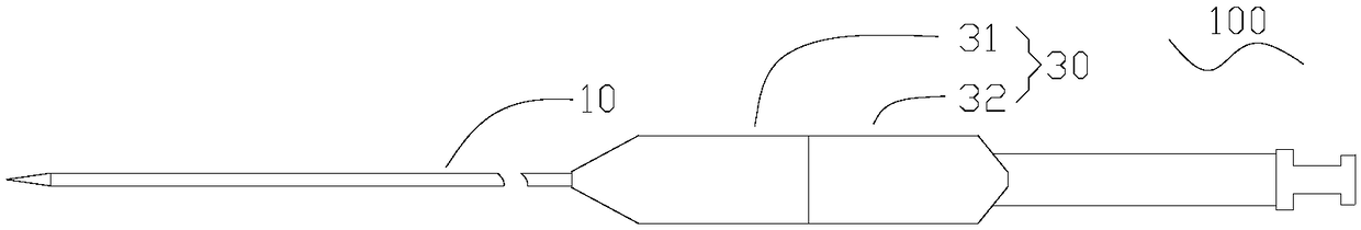
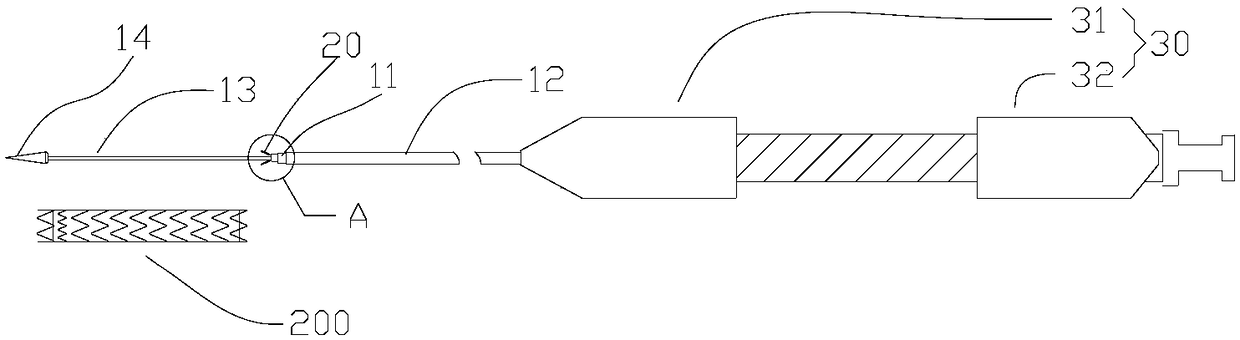
[0049] See also Figure 1a to Figure 1c , the delivery system 100 provided in Embodiment 1 is used to deliver the implant to the lesion in the lumen of the human body. The delivery system 100 includes a tube body 10 , an anchor unit 20 , and a handle 30 . In this embodiment, the implant is a lumen stent 200 .

[0050] The handle 30 includes a first shell 31 and a second shell 32 which are symmetrically arranged. The first housing 31 and the second housing 32 can move relative to each other in the axial direction, and the first housing 31 is closer to the distal end than the second housing 32 .

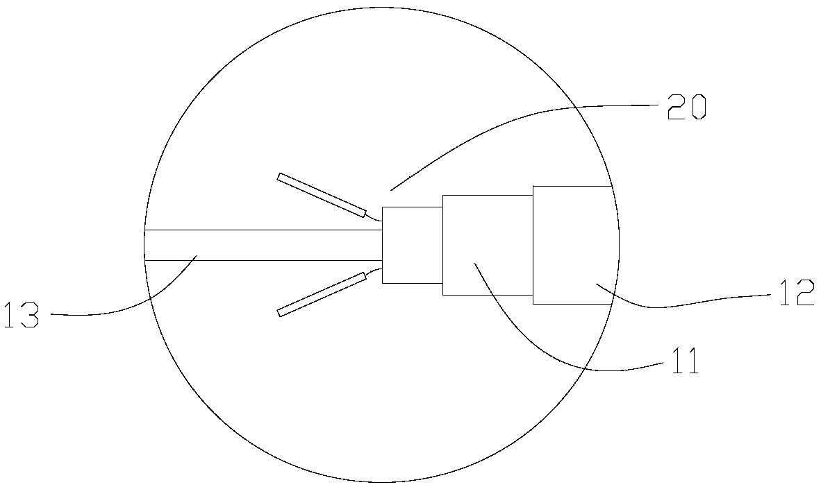
[0051] The tube body 10 includes a hollow inner sheath tube 11 axially penetrating through the handle 30, a hollow inner sheath core tube 13 penetrating through the inner sheath tube 11 and protruding from the inner sheath tube 11 at the distal end, and movably sleeved on the inner sheath tube 11 An outer sheath tube 12 with a cavity on the outside and between the inner sheath core t...

Embodiment 2

[0097] The structure of the endoluminal stent delivery system provided in this embodiment is basically the same as that of the endoluminal stent delivery system 100 provided in the first embodiment. The difference is that, in this embodiment, the structure of the tightening piece, the number and structure of the anchoring pieces are different from those of the first embodiment.

[0098] Specifically, see Figure 6a , in this embodiment, the anchoring unit 40 includes a sleeve-shaped tightening member 41 with a certain wall thickness, and at least one anchoring member 42 connected to the tightening member 41 .

[0099] Please also see Figure 6b , The tightening member 41 has at least one pair of guide holes 411 . The guide hole 411 includes a first hole 411a located on the distal end surface of the tightening member 41, and a second hole 411b located on the outer wall of the tightening member 41, and the first hole 41a and the second hole 41b are connected, A pair of guide ...

Embodiment 3

[0111] The structure of the endoluminal stent delivery system provided in this embodiment is basically the same as that of the endoluminal stent delivery system 100 provided in the first embodiment. The difference is that in this embodiment, the structure of the inner sheath core tube and the tightening parts, the number and structure of the anchor parts are the same as those of the inner sheath core tube and the tightening parts, the number and structure of the anchor parts in the first embodiment. The structures are all different.

[0112] Specifically, see Figure 9a , in this embodiment, the anchoring unit 50 includes a sleeve-shaped tightening member 51 and five anchoring members 52 connected to the tightening member 51 . The anchoring part 52 includes a deformation part 521 connected to the tightening part 51 and a spherical locking part 522 connected to the deformation part 521 .

[0113] The anchoring unit 50 is laser-engraved from a nickel-titanium tube whose wall t...


PUM

PropertyMeasurementUnit
Lengthaaaaaaaaaa

Abstract

The invention discloses an implant delivery system, comprising an inner sheath core tube, an outer sheath tube with a cavity and movably sleeves the outside of the inner sheath core tube, and at leastone anchoring unit fixed to the outer surface of the inner sheath core tube, wherein each anchoring unit comprises a hooping member sleeving the outer surface of the inner sheath core tube, and at least one anchoring member connected with the hooping member, each anchoring member comprises a deformation part which can bend relative to the inner sheath core tube and a locking part connected with the deformation part, and when the deformation parts and the locking parts are accommodated in the cavity between the outer sheath tube and the inner sheath core tube, anchors are formed in combinationwith the hooping members. An implant is fixed onto the inner sheath core tube by the anchoring units to limit the movement of the implant. Thus, during the delivery of the implant, the implant is notdeviated from the inner sheath core tube. In the process of release, when the release position of the implant needs to be adjusted, the early release of the implant can be avoided.

Description

technical field [0001] The invention relates to an implantable medical device, in particular to a delivery system for the implant. Background technique [0002] For diseases such as vascular stenosis, aneurysm, and vascular dissection, interventional surgery with luminal stents has the advantages of less trauma, faster recovery, fewer complications, and better therapeutic effects. [0003] The metal skeleton structure of the self-expanding stent luminal stent is usually made of nickel-titanium alloy, and after a heat setting process, the luminal stent has the ability to restore its own shape. At present, the tube body of the delivery system of this type of stent generally includes an outer sheath tube and an inner sheath core tube pre-installed in the outer sheath tube. The proximal end of the inner sheath core tube is thicker and the distal end is thinner. The lumen stent is accommodated in the cavity between the outer sheath tube and the distal part of the inner sheath co...

Claims


Application Information

Patent Timeline
IPC IPC(8): A61F2/966
CPCA61F2/966
Inventor 王逸斐肖本好
Owner LIFETECH SCIENTIFIC (SHENZHEN) CO LTD
Learn More