Multi-station flexible stamping workstation

A workstation and multi-station technology, applied in the field of mechanical processing, can solve the problems of complicated and long-time mold conversion process, difficult to control the quality of stamping products, large and complex equipment, etc., to achieve strong product specifications universality, easy production management, Reduce the effect of manual operations

Pending Publication Date: 2019-01-25
GSK CNC EQUIP
View PDF1 Cites 3 Cited by
  • Summary
  • Abstract
  • Description
  • Claims
  • Application Information

AI Technical Summary

Problems solved by technology

However, this device has disadvantages such as poor safety, relatively large and complex equipment, high failure rate, complex and long-term process of changing production and die, and it is difficult to control the quality of stamping products

Method used


Image

  • Multi-station flexible stamping workstation
  • Multi-station flexible stamping workstation
  • Multi-station flexible stamping workstation

Examples


Embodiment 1

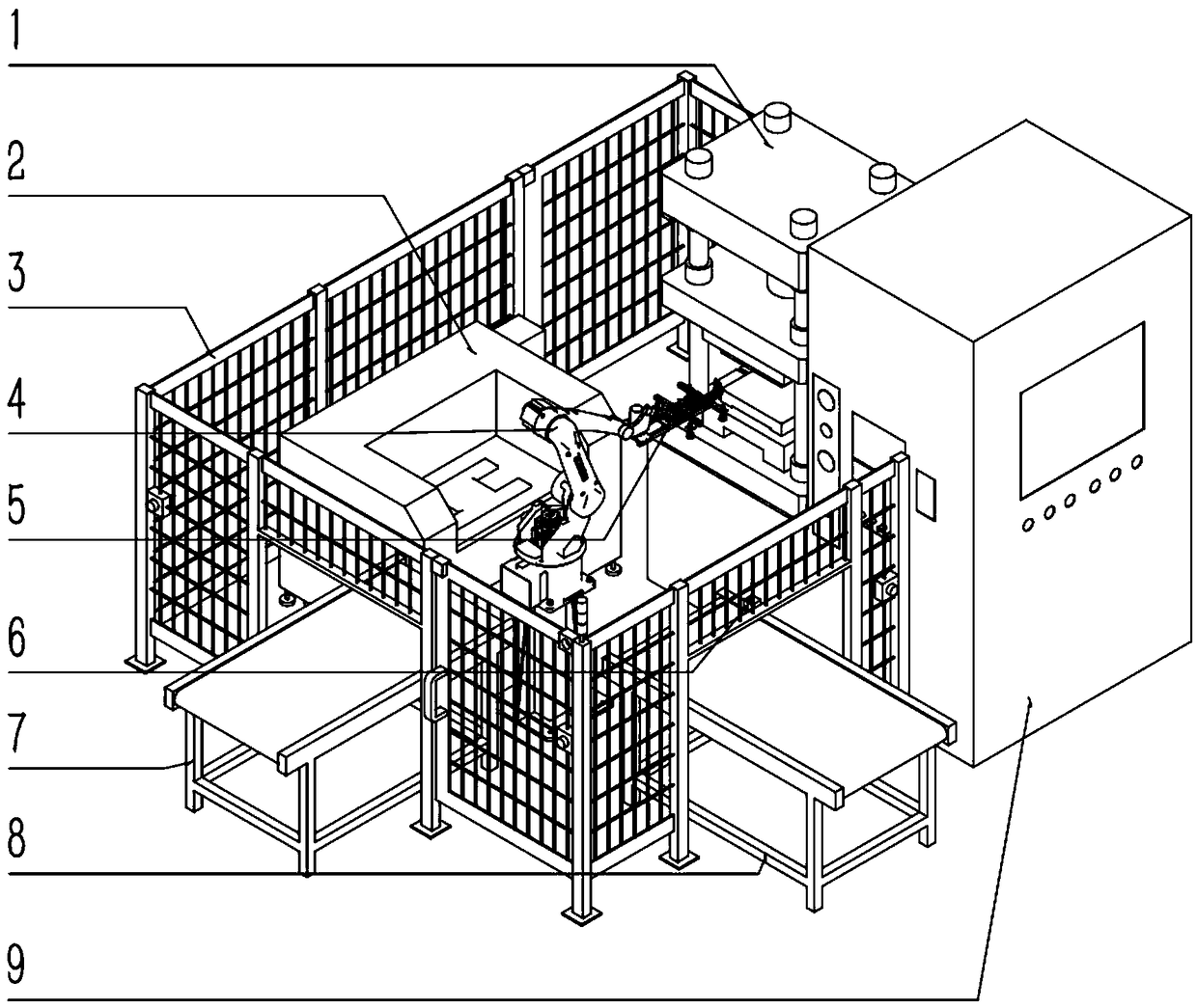
[0024] Such as figure 1 As shown, a multi-station flexible stamping workstation includes a punch (1), a laser cutting machine (2), a safety fence (3), a multi-joint industrial robot (4), a robot gripper (5), and a vision camera (6). ), the discharge conveyor line (7), the input conveyor line (8), and the stamping die library (9).

[0025] Such as figure 1 , The safety fence (3) is connected with the two sides of the stamping die library (9), and the safety fence (3) and the stamping die library (9) define the space range of the flexible working space. The punch (1), the laser cutting machine (2), the articulated industrial robot (4), the robot gripper (5) and the vision camera (6) are arranged inside the working space, the discharge conveyor line (7) and the input The material conveying line (8) extends through the working space and is used for docking with the upper process and the next process in the production line. The industrial robot (4) is connected with the discharging c...

Embodiment 2

[0036] Such as Figure 4 As shown, Embodiment 2 is suitable for methods that do not need to be connected to other production lines. In Example 2, an aggregater (10) and a feeder (11) are used instead of the discharge conveyor line (7) and the feed conveyor line (8) described in Example 1, which are used in the production line and the upper and lower channels Process docking, other components and their structures are the same as in Example 1.

[0037] The aggregater (10) and the feeder (11) each have two independent stations to facilitate the loading and unloading of the system during operation; the distance between the limit stops of each independent station can be driven by pneumatic or The electric drive realizes distance adjustment to suit the storage of stamping products of different specifications. When changing the production to replace the stamping die, the system will read the corresponding product size of the die and automatically adjust the distance between the indepe...


PUM


Abstract

The invention discloses a multi-station flexible stamping workstation which comprises a punching machine, safe protective guards, a multi-joint industrial robot, a discharged material conveying line,a fed material conveying line and a stamping die library. The safe protective guards are connected with two side surfaces of the stamping die library, the safe protective guards and the stamping die library limit flexible working space, the punching machine, the multi-joint industrial robot and a visual camera are arranged in the working space, the discharged material conveying line and the fed material conveying line extend and penetrate the working space, the punching machine, the discharged material conveying line and the fed material conveying line are arranged on the peripheral side of the multi-joint industrial robot, and the stamping die library is arranged on the side surface of the punching machine. According to the workstation, high quality of a stamping product is ensured, the workstation is high in automation degree and production efficiency, safe and reliable, production management is facilitated, and zero-clearance connection and real-time control are achieved after a production line is changed.

Description

Technical field [0001] The invention relates to the field of mechanical processing, in particular to a multi-station flexible stamping workstation. Background technique [0002] At present, most of the stamping industry is still operated manually, and there is a problem of high safety risks. Stamping operators need to have direct and continuous contact with the machine and the workpiece, and operator safety accidents occur from time to time; workers working in the stamping workshop for a long time, high-intensity repeated operations, people are prone to fatigue and boredom, and are affected by the noise emitted by the workshop equipment , The auditory system of press workers may be damaged; at the same time, there are occupational hazards such as vibration, which will damage the skin sensory function. [0003] Patent 201620386082.2 discloses an integrated automatic punching workstation. The automatic punching workstation in this patent specifically includes a base, a press, a punc...

Claims


Application Information

Patent Timeline
Patent Type & Authority Applications(China)
IPC IPC(8): B21D22/02B21D43/18B21D55/00B21C51/00B23K26/38B23P23/06B08B5/02
CPCB21D22/02B08B5/02B21C51/00B21D43/18B21D55/00B23K26/38B23P23/06
Inventor 钱立江文明
Owner GSK CNC EQUIP
Why Eureka
Try Eureka