Liquid crystal phased array-based laser radar system

A technology of laser radar and laser emission system, which is applied in the field of laser phase control, can solve the problems of light intensity loss, beam deflection system use limitation, etc., and achieve the effect of reducing light loss, reducing light intensity loss, and reducing data processing time

Active Publication Date: 2019-02-01
CHANGCHUN UNIV OF SCI & TECH
View PDF5 Cites 18 Cited by
  • Summary
  • Abstract
  • Description
  • Claims
  • Application Information

AI Technical Summary

Problems solved by technology

[0004] In order to solve the problem that the incident light and the outgoing light are separated by using a light splitting device in the optical path, the introduction of the light splitting device will cause the loss of light intensity, so that the use of the beam deflection system is limited, and a laser based on liquid crystal phased array is provided. radar system

Method used


Image

  • Liquid crystal phased array-based laser radar system
  • Liquid crystal phased array-based laser radar system
  • Liquid crystal phased array-based laser radar system

Examples


specific Embodiment approach 1

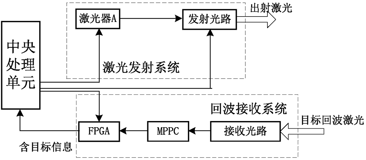
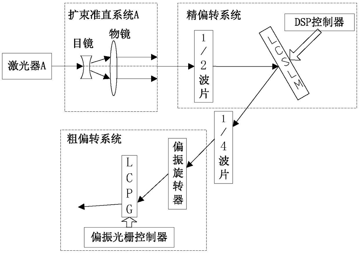
[0029] Specific implementation mode 1. Combination Figure 1 to Figure 3 To illustrate this embodiment, a laser radar system based on a liquid crystal phased array includes a central processing unit, a laser emitting system, and an echo receiving system; the laser emitting system includes a laser, and an emitting optical path; the emitting optical path includes a beam expander collimation system , fine deflection system, 1 / 4 wave plate, coarse deflection system; said fine deflection system includes 1 / 2 wave plate, LCSLM and DSP controller; said coarse deflection system includes liquid crystal polarization rotator, liquid crystal polarization grating and polarization grating Controller; the echo receiving system includes FPGA, multi-pixel photon counter (MPPC) and receiving optical path;

[0030] The central processing unit controls the laser to emit laser light, and at the same time sends instructions to the FPGA, and the FPGA starts timing. Among them, the central processing...

specific Embodiment approach 2

[0033] Specific embodiment two, combine Figure 4 to Figure 9To illustrate this embodiment, the phase modulation system is constructed by using the principle of polarization interference, and the phase modulation characteristic curve of the LCSLM at an incident angle of 20° is obtained by measuring the interference result of two polarization components in a beam of light. The phase delay measurement system of LCSLM under oblique incidence includes: laser B, beam expander collimation system B, half-wave plate, polarizer P1 and polarizer P2.

[0034] A beam of 1064nm linearly polarized light emitted by the laser is expanded and collimated, then passes through a half-wave plate to produce linearly polarized light in the same direction as the optical axis of the liquid crystal optical phased array, and then passes through the polarizer P1 to incident on the LCSLM at an angle of 20°. Polarizer P1, so that the optical axis of polarizer P1 forms an angle of 45° with the fast axis of ...


PUM


Abstract

The invention provides a liquid crystal phased array-based laser radar system, and relates to the technical field of laser phase control. By the liquid crystal phased array-based laser radar system, the problem that incident light and emergent light are separated by a light splitter in an existing light path and the light intensity loss can be caused by introduction of the light splitter so that the application of a beam deflection system is limited are solved. The liquid crystal phased array-based laser radar system comprises a central processing unit, a laser emission system and an echo receiving system, wherein the laser emission system comprises a laser A and an emission light path, the emission light path comprises a beam expansion collimation system A, a refined deflection system, aone fourth wave plate and a rough deflection system, the refined deflection system comprises a one second wave plate, a liquid crystal spatial light modulator (LCSLM) and a DSP controller, the rough deflection system comprises a liquid crystal polarization rotator, a liquid crystal spatial light modulator (LCPG) and a polarization grating controller, and the echo receiving system comprises a fieldprogrammable gate array (FPGA), an MPPC and a receiving light path. An oblique incidence mode is employed, an included angle between light irradiating the liquid crystal spatial light modulator and emergent light is increased, the light path is simplified, the system volume is reduced, the light intensity loss caused by the light splitter is also reduced, and the application range of the liquid crystal spatial light modulator is expanded.

Description

technical field [0001] The invention relates to the technical field of laser phase control, in particular to a laser phased array radar system with wide field of view, high precision and high diffraction efficiency. Background technique [0002] Compared with other institutional radars, lidar has a higher carrier frequency. Compared with microwave radar, it has higher resolution in speed measurement, angle measurement and distance measurement, and has the advantages of long range, strong anti-interference ability, and the ability to obtain multiple images of targets. Therefore, it is used in target detection, target imaging, and target speed measurement. , target tracking and other fields have received extensive attention and become a research hotspot. The traditional laser radar system realizes beam scanning by driving the mechanical rotation mechanism through the servo system, but due to the large size of the servo system, high power consumption, poor vibration resistance...

Claims


Application Information

Patent Timeline
Patent Type & Authority Applications(China)
IPC IPC(8): G01S7/481G01S7/484G01S7/486G01S7/491
CPCG01S7/481G01S7/484G01S7/486G01S7/4911G01S7/4912
Inventor 王春阳牛启凤史红伟李兰婷
Owner CHANGCHUN UNIV OF SCI & TECH
Why Eureka
Try Eureka