Permanent magnet synchronous motor rotor with air magnetic barrier

A technology for permanent magnet synchronous motors and magnetic barriers, applied in the direction of magnetic circuit rotating parts, magnetic circuits, electrical components, etc., can solve the problems of weak magnetic field speed expansion capability SPMSM, increased stator loss, and the risk of irreversible demagnetization of permanent magnets. To achieve the effect of improving the speed expansion capability of magnetic field weakening, expanding the constant power range, and reducing the risk of demagnetization

Pending Publication Date: 2019-02-15
SHANGHAI TOP MOTOR
View PDF0 Cites 0 Cited by
  • Summary
  • Abstract
  • Description
  • Claims
  • Application Information

AI Technical Summary

Problems solved by technology

[0006] However, the traditional structure of SPMSM has the following defects for a long time: the permanent magnet is usually tile-shaped (arc-shaped) and located on the outer surface of the rotor core. Since the relative recovery permeability of the permanent magnet is close to that of air, the air gap between the orthogonal and direct axes Uniform, alternating and direct axis inductance are equal (Ld=Lq), electromagnetic performance belongs to the hidden pole magnetic circuit, does not generate reluctance torque, and because the equivalent air gap is larger, it is more difficult to solve the weak magnetic speed expansion than IPMSM, must A large direct-axis current is passed into the stator winding to achieve the purpose of field weakening and speed expansion. This method will reduce the torque, increase the stator loss, reduce the efficiency of the drive system, and the power density is low, and may cause permanent magnets to be irreversible. The danger of demagnetization and the poor speed expansion ability of weak magnetic field are the fundamental reasons hindering the high-speed development of SPMSM

Method used


Image

  • Permanent magnet synchronous motor rotor with air magnetic barrier
  • Permanent magnet synchronous motor rotor with air magnetic barrier
  • Permanent magnet synchronous motor rotor with air magnetic barrier

Examples


Embodiment Construction

[0021] The embodiments of the present invention are described in further detail below in conjunction with the accompanying drawings, but the present embodiments are not intended to limit the present invention. All similar structures and similar changes of the present invention should be included in the scope of protection of the present invention. The commas in all represent the relationship between and, and the English letters in the present invention are case-sensitive.

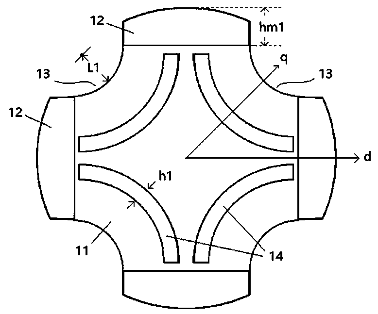
[0022] Such as figure 1 As shown, the permanent magnet synchronous motor rotor with an air magnetic barrier provided by the first embodiment of the present invention includes a rotor core 11 and a plurality of surface magnets 12 fixed on the outer peripheral surface of the rotor core, and each surface magnet surrounds the rotor core The axisymmetric spacing of the layout;

[0023] The middle part of the surface magnet 12 protrudes outward in an arc shape along the radial direction of the rotor core 11, so ...


PUM


Abstract

The invention discloses a permanent magnet synchronous motor rotor with an air magnetic barrier, relates to the technical field of motors, and solves the technical problem that the flux-weakening speed expansion capacity is improved. The rotor comprises a rotor core and a plurality of surface magnets fixed to the peripheral surface of the rotor core, wherein the surface magnets are symmetrically arranged around the axis of the rotor core at intervals; the middle parts of the surface magnets are raised in the shapes of arcs outwards along the radial direction of the rotor core, so that the surface magnets in the radial cross section of the rotor core are in the shapes of breads with thick middle part and two thin sides, and each surface magnet is divided into two symmetrical halves by the direct axis of the rotor core; a plurality of surface magnetic barrier grooves which are hollow inwards in the radical directions are formed in the peripheral surface of the iron core, the surface magnetic barrier grooves are formed among the surface magnets, each surface magnetic barrier groove is formed between every two corresponding adjacent surface magnets, and each surface magnetic barrier groove is divided into two halves by the quadrature axis of the iron core. According to the rotor provided by the invention, the dynamic performance of the motor can be improved.

Description

technical field [0001] The invention relates to motor technology, in particular to a permanent magnet synchronous motor rotor technology with an air magnetic barrier. Background technique [0002] The motor is the core of the electric drive system, and the performance and efficiency of the motor directly affect the performance of the electric vehicle. At present, the wide speed regulation and high torque permanent magnet synchronous motor (PMSM) used in electric vehicles still has technical bottlenecks, such as low power density, narrow high-speed constant power range, large torque fluctuation, low overload capacity and poor reliability. Difficult to meet requirements. [0003] According to the different configuration positions of the rotor permanent magnets, PMSM can be divided into two categories: surface-mounted permanent magnet rotor structure and built-in permanent magnet rotor structure. [0004] The advantage of the built-in permanent magnet synchronous motor (IPMSM...

Claims


Application Information

Patent Timeline
Patent Type & Authority Applications(China)
IPC IPC(8): H02K1/27
CPCH02K1/278H02K2213/03
Inventor 林德芳
Owner SHANGHAI TOP MOTOR
Why Eureka
Try Eureka