A self-driving drive circuit for a dual-transistor forward synchronous rectification circuit
A technology of synchronous rectification and drive circuit, which is applied in the direction of high-efficiency power electronic conversion, electrical components, output power conversion devices, etc., can solve the problems of reducing the efficiency of the converter, unable to provide driving voltage for the freewheeling tube, etc., to improve reliability Sexuality, easy implementation and practicality, effect of size reduction
- Summary
- Abstract
- Description
- Claims
- Application Information
AI Technical Summary
Problems solved by technology
Method used
Image
Examples
no. 1 example
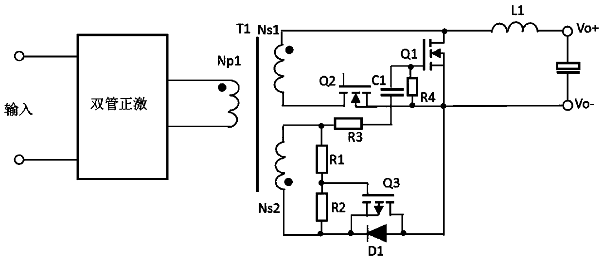
[0028] figure 1 The circuit schematic diagram of the first embodiment is shown, following the connection relationship of the above-mentioned initial technical scheme, a self-driving drive circuit of a dual-tube forward synchronous rectification circuit, the dual-tube forward synchronous rectification circuit includes a transformer, and The double-transistor forward network on one side and the synchronous rectification transformation network on the secondary side of the transformer; the transformer includes the first primary winding Np1, the first secondary winding Ns1 and the second secondary winding Ns2, and the synchronous rectification transformation network on the secondary side of the transformer includes The first secondary winding Ns1, the freewheeling tube Q1 whose drain is connected to the same-named end of the first secondary winding Ns1, the inductor L1 connected to the drain of the freewheeling tube Q1 at one end, and the other end of the inductor L1 is the output o...
no. 2 example
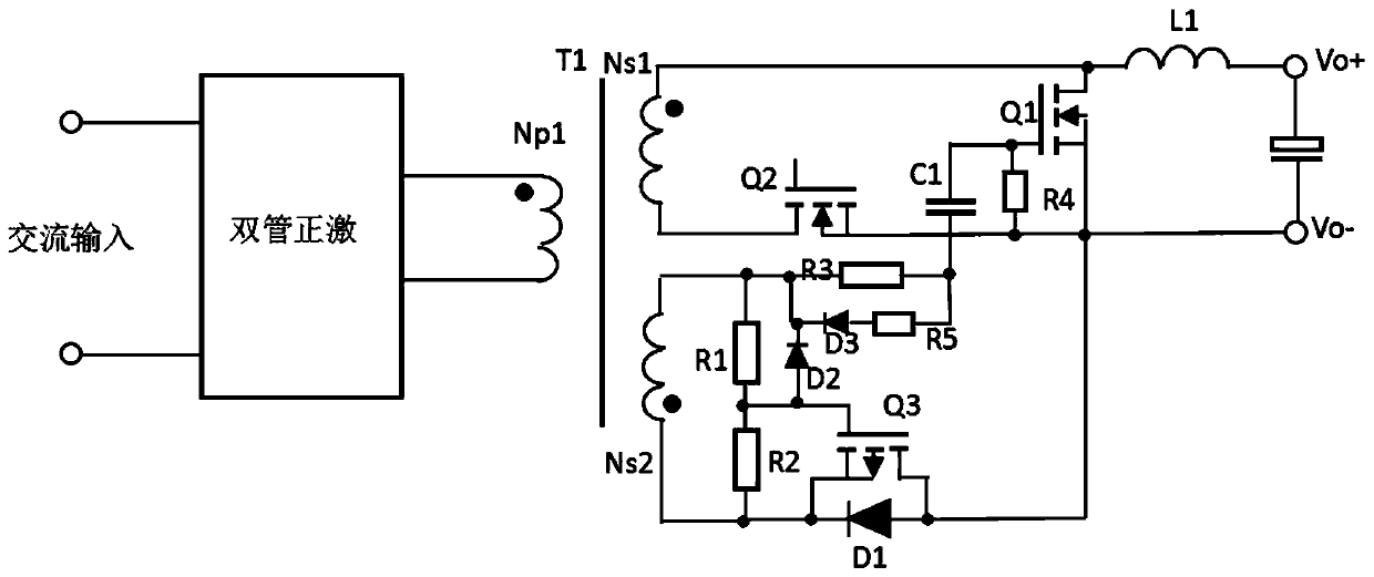
[0037] figure 2 shows the schematic diagram of the circuit of the second embodiment, and the difference from the first embodiment is that in the first embodiment figure 1 On the basis of , a diode D2 is connected between the gate of the first P-type MOS transistor and the opposite terminal of the second secondary winding Ns2 of the transformer, which can accelerate the discharge of the gate-source voltage of the first P-type MOS transistor Q3, so that The first P-type MOS transistor Q3 is quickly turned on, so that the freewheeling transistor Q1 is quickly turned off. At the same time, a series circuit composed of a resistor R5 and a diode D3 is connected in parallel at both ends of the third resistor R3. The cathode of the diode D3 is connected between the opposite end of the second secondary winding Ns2 and the resistor R3, and the anode of the diode D3 is connected after the resistor R5. Connected between the resistor R3 and the first capacitor C1. In this way, the disch...
no. 3 example
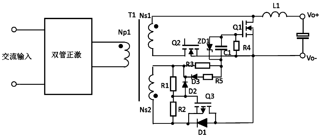
[0039] image 3 shows the schematic diagram of the circuit of the third embodiment, the difference from the second embodiment is that in the second embodiment figure 2 On the basis of , the voltage regulator tube ZD1 is connected in parallel at both ends of the first capacitor C1, the anode of the voltage regulator tube ZD1 is connected to the gate connection point of the first capacitor C1 and the freewheeling tube Q1, and the cathode of the voltage regulator tube ZD1 is connected to the first capacitor C1 and the resistor The connection point of R3 and resistor R5, the presence of Zener tube ZD1 can control the maximum bias voltage at both ends of the first capacitor C1, preventing the bias voltage at both ends of the first capacitor C1 from being too high and causing the gate-source voltage of the freewheeling tube Q1 to be too low As a result, the freewheeling tube cannot be turned on normally.
PUM
 Abstract
Description
Claims
Application Information
 - R&D
- Intellectual Property
- Life Sciences
- Materials
- Tech Scout
- Unparalleled Data Quality
- Higher Quality Content
- 60% Fewer Hallucinations
Browse by: Latest US Patents, China's latest patents, Technical Efficacy Thesaurus, Application Domain, Technology Topic, Popular Technical Reports.
© 2025 PatSnap. All rights reserved.Legal|Privacy policy|Modern Slavery Act Transparency Statement|Sitemap|About US| Contact US: help@patsnap.com


