Laser plastic welding method and plastic product

A laser welding and plastic technology, applied in the field of laser welding, can solve the problems of inability to efficiently absorb laser energy, unusable, unstable welding, etc., and achieve the effect of solving plastic surface burns, reducing welding processes, and reducing welding costs.

Active Publication Date: 2019-02-19
HANS LASER TECH IND GRP CO LTD
View PDF8 Cites 6 Cited by
  • Summary
  • Abstract
  • Description
  • Claims
  • Application Information

AI Technical Summary

Problems solved by technology

However, the transparent TPU material is soft and cannot be welded by ultrasonic waves, and glue is often used.
Lasers with a wavelength of 915nm-980nm cannot be absorbed by transparent TPU materials, and are mostly used for welding products with light-transmitting upper layers and light-absorbing lower layers. In order to achieve welding, absorbents need to be added, which increases the cost of plastic welding. Instability factors, on the other hand, the absorption of the absorbent components sprayed by organisms may also have

Method used


Image

  • Laser plastic welding method and plastic product
  • Laser plastic welding method and plastic product
  • Laser plastic welding method and plastic product

Examples


Embodiment 1

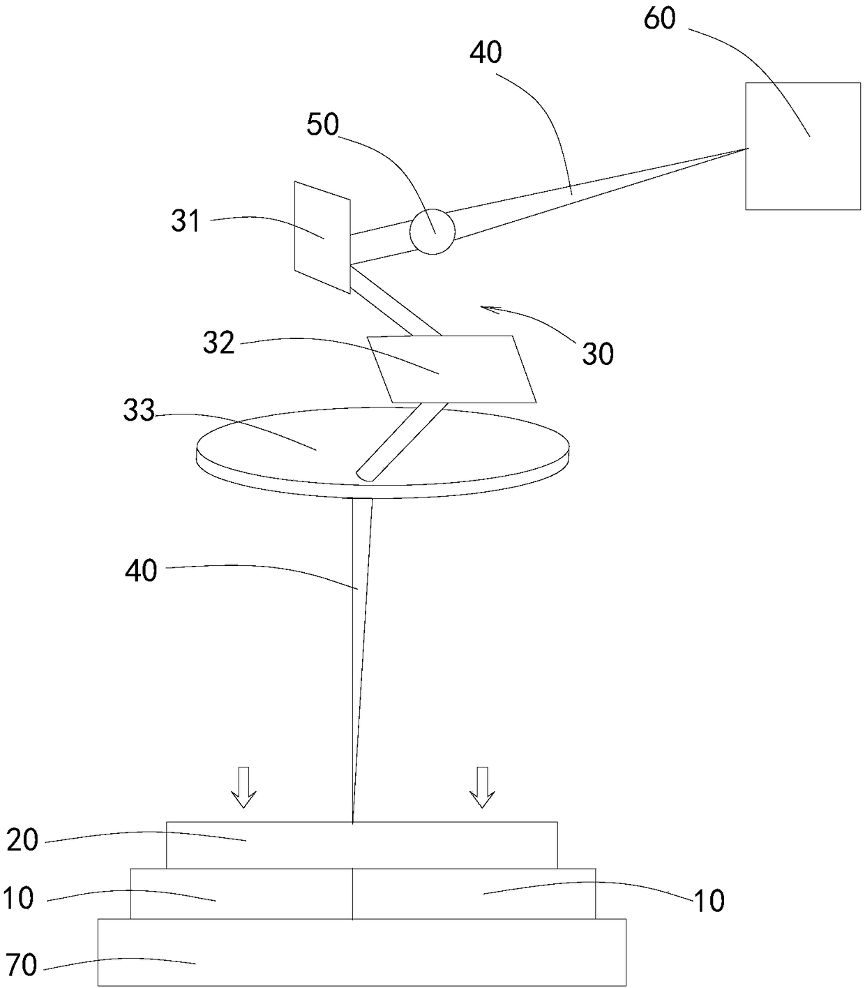
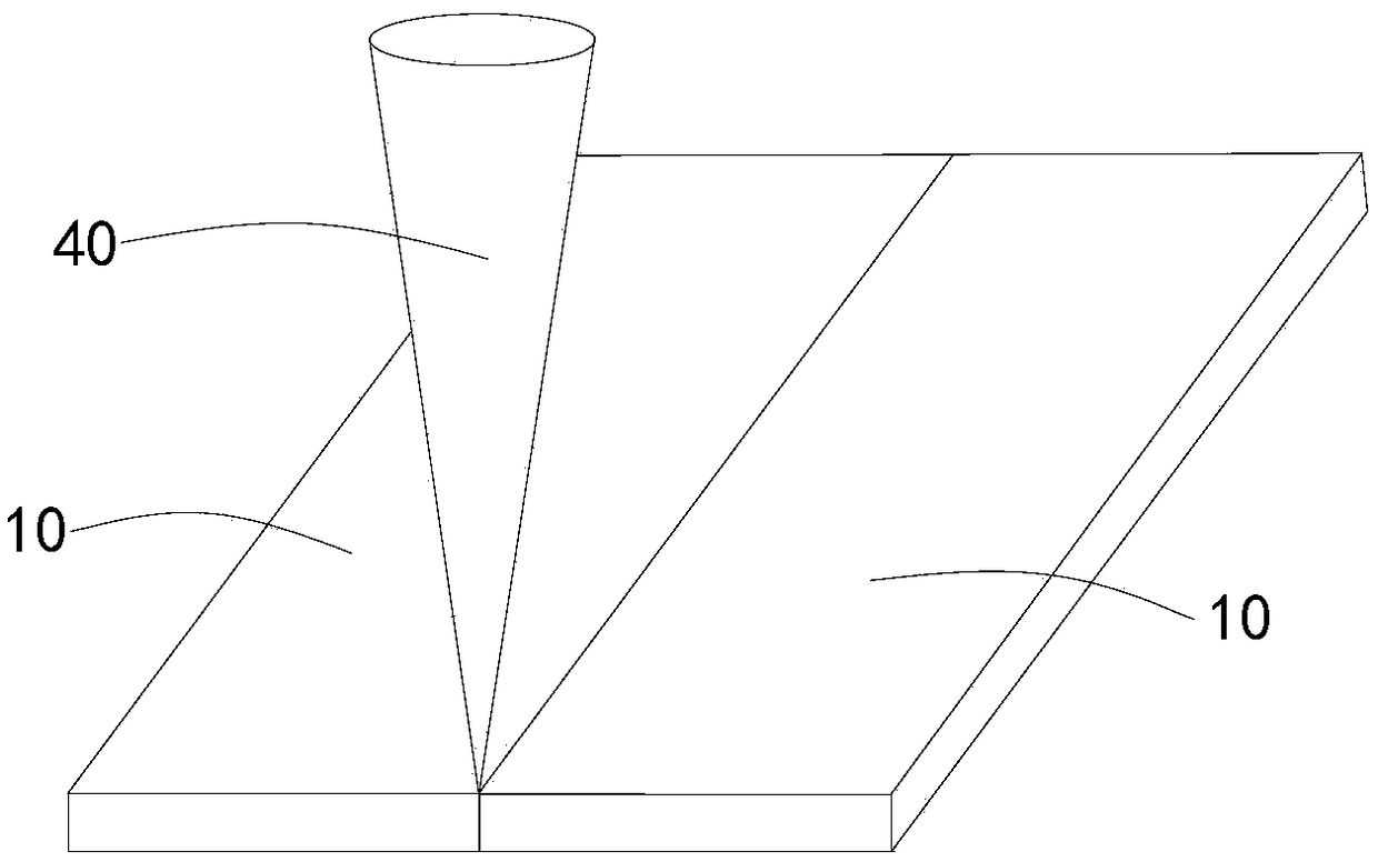
[0045] Please refer to figure 1 , The present invention provides a method for laser welding plastics, which is to butt-weld two pieces of 1mm thick transparent PA plastic 10 together, which includes the following steps: placing two pieces of plastic 10 on a metal workbench 70 and butt together, A sapphire cover 20 is pressed on the top surface of the two pieces of plastic 10 with a thermal conductivity of 45W / (m·K). The pressure of the sapphire cover 20 is guaranteed to be 100N, and a sapphire cover 20 with a wavelength of 1940nm is set above the sapphire cover 20 Mid-infrared thulium-doped fiber laser 60 and galvanometer 30. The diameter of the fiber laser 60 is 400um, the power is about 20W, and the maximum power is 30W. The galvanometer 30 is set near the fiber laser 60 to ensure that the fiber laser 60 emits The laser beam 40 can be transmitted to the galvanometer 30; turn on the fiber laser 60, the fiber laser 60 emits a laser beam 40, the laser beam 40 is transmitted to th...

Embodiment 2

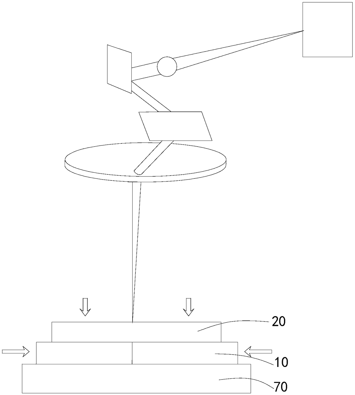
[0050] Please refer to image 3 The difference from the first embodiment is that before the fiber laser 60 is turned on, a pressure of 40N is applied to the opposite sides of the two pieces of plastic 10 far away from the butting gap. After the fiber laser 60 is turned on, the two pieces of plastic 10 are pressed on the left and right sides. A weld is formed under the action to ensure that the butt joint position is fit. If the butt joint of the two pieces of plastic 10 is curved, the laser beam 40 scans along the curved butt joint.

Embodiment 3

[0052] The difference between this embodiment and the first embodiment is that the material of the two pieces of plastic 10 is PET material. After monitoring, the absorption rate of the 1940 nm mid-infrared thulium-doped laser is 85%-90%.


PUM

PropertyMeasurementUnit
Wavelengthaaaaaaaaaa
Thermal conductivityaaaaaaaaaa
Fiber diameteraaaaaaaaaa

Abstract

The invention discloses a laser plastic welding method and a plastic product. The method comprises the following steps that at least two pieces of plastic are butt-jointed or stacked together, and a heat-conduction cover plate is arranged on the top surfaces of the plastic in a pressing manner; a mid-infrared thulium-doped optical fiber laser with the wavelength being 1,940 nm and a galvanometer are arranged above the heat-conduction cover plate; the optical fiber laser is started and emits a laser beam, the laser beam is transmitted onto the galvanometer and moves along the heat-conduction cover plate according to the preset scanning path after passing through the galvanometer, the plastic absorbs the energy of the laser beam passing through the heat-conduction cover plate, and thus welding is completed; and the plastic product is produced with the laser plastic welding method. With the laser plastic welding method, efficient welding can be realized, additive pollution can be reduced,the welding cost can be reduced, the performance of the welded product is stable, and the surface layers of the plastic can be prevented from being burnt.

Description

Technical field [0001] The invention relates to the technical field of laser welding, in particular to a method for laser welding plastics and plastic products. Background technique [0002] Laser plastic welding is a new type of plastic processing method. Laser plastic welding has the characteristics of clean and efficient, and it is increasingly used. [0003] Biological ear tags are animal identifications applied to biological ears to identify biological identities. They are often used to identify and track livestock, help control animal diseases and improve the management level of farms. Biological ear tags are commonly used in TPU plastic shells with built-in chips. The transparent TPU material is soft, so welding methods such as ultrasonic cannot be used, and adhesive methods are mostly used. Lasers with wavelengths of 915nm-980nm cannot be absorbed by transparent TPU materials. They are mostly used for welding products where the upper layer is transparent and the lower lay...

Claims


Application Information

Patent Timeline
IPC IPC(8): B29C65/16
CPCB29C65/16B29C66/733B29C66/90
Inventor 刘维波黄裕佳闵彬周继伟苏长鹏王瑾高云峰
Owner HANS LASER TECH IND GRP CO LTD
Why Eureka
Try Eureka