Core test device for high temperature and high pressure hydraulic fracturing and triaxial test

A hydraulic fracturing, high temperature and high pressure technology, applied in the direction of applying stable tension/pressure to test the strength of materials, measuring devices, instruments, etc., can solve the complex disassembly process of test instruments, the limitation of the convenience of test devices, and the long cooling time of high temperature oil and other problems, to achieve the effect of shortening the test cycle, simple structure, and easy to constrain the angle

Pending Publication Date: 2019-02-19
JILIN UNIV
View PDF0 Cites 6 Cited by
  • Summary
  • Abstract
  • Description
  • Claims
  • Application Information

AI Technical Summary

Problems solved by technology

The tightness of the test device is related to the accuracy of simulating high-pressure conditions. A good test device can not only meet the pressure conditions of deep underground rock mass, but also improve the efficiency of the test; due to the high temperature and high pressure requirements of the test conditions, the test device Convenience is limited to a large extent, both high temperature resistance and high pressure resistance must be considered, which makes the disassembly process of most related test instruments complicated, the cooling time of high temperature oil is long, and the test cycle is slow

Method used


Image

  • Core test device for high temperature and high pressure hydraulic fracturing and triaxial test
  • Core test device for high temperature and high pressure hydraulic fracturing and triaxial test
  • Core test device for high temperature and high pressure hydraulic fracturing and triaxial test

Examples


Embodiment 1

[0037] Examples of hydraulic fracturing

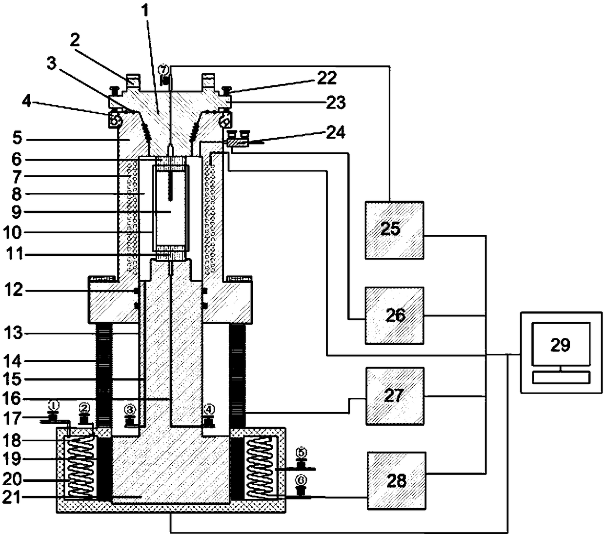
[0038] Step 1, processing the rock core, the rock core is processed by a rock sample cutting machine into a cylindrical shape, and the axis has a water guide hole of a certain depth;

[0039] Step 2: Carry out core clamping outside the cavity 8, respectively place the top pad 6, the rock sample 9, and the bottom pad 11 in the order of upper, middle, and lower, and put them in the high-elastic rubber sleeve 10, and the sleeve The upper and lower ends can be sealed with a closing device;

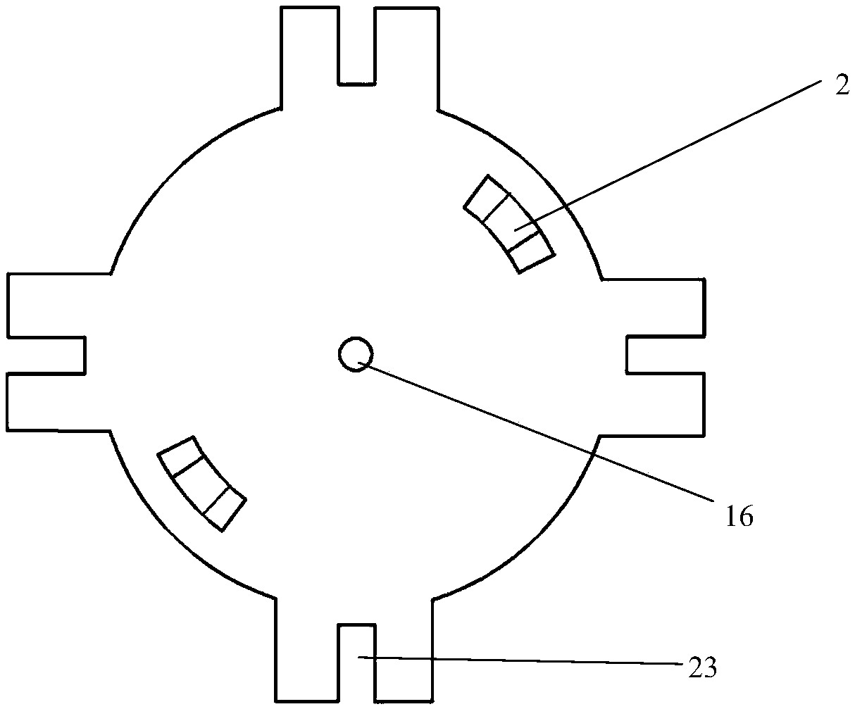
[0040] Step 3, use a rod-shaped device to cooperate with the removal of the auxiliary hole 2, rotate the top tapered threaded plug 1, and open the upper opening of the cylinder 5;

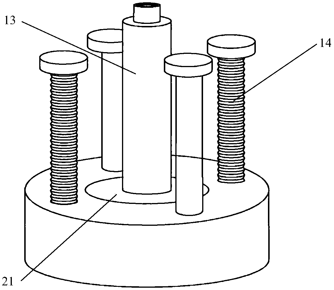
[0041] Step 4, turn on the computer system 9, control the lifting controller 27, and make the cylinder body 5 descend along the threaded axial guide rail 14 until the top of the axial plunger 13 rises to the opening of the cylinder body 5;

[0042] Step 5, insert the clam...

Embodiment 2

[0053] HTHP triaxial embodiment

[0054] Replacement of ordinary pads without applying hydraulic pressure, the steps repeat the steps of the hydraulic fracturing embodiment, and use the servo hydraulic machine 21 to push the axial plunger 13 to apply pressure until the rock sample 9 is destroyed.


PUM


Abstract

The invention relates to a core test device for high temperature and high pressure hydraulic fracturing and triaxial test. The core test device is composed of a top conical thread plug, a dismountingauxiliary hole, an O-shaped sealing ring, a movable bolt ring, a cylinder body, a top cushion block, a heating resistance wire, a cavity, a rock sample, a high elastic rubber sleeve, a bottom cushionblock, a stepseal, an axial direction plunger, an axial direction bolt guide rail, an oil guide hole, a central water guide hole, a condensing pipe, a thermal insulation protective layer, a heat transfer of cooling chamber, a servo hydraulic press, a bolt, a constraint slot, a high-voltage four-way valve, a hydraulic pump, a confining pressure pump, a lifting controller, an oil box, a computer system, and a high-voltage ball valve. The test device is simple in structure, convenient to detach, good in sealing performance, capable of rapidly replacing rock cores, and capable of performing different core mechanical property tests under various temperatures and pressure conditions according to scientific research and production requirements, the system comprises a core triaxial test and a hydraulic fracturing test, and the working efficiency is high and reliable.

Description

technical field [0001] The invention relates to a test device, in particular to a core test device for high-temperature, high-pressure triaxial and hydraulic fracturing. Background technique [0002] As a new energy source, hot dry rock has the advantages of large reserves, wide distribution range, clean and pollution-free, and has attracted the attention of researchers. However, due to the large burial depth of hot dry rock, low reservoir permeability and high in-situ stress, the thermal energy exchange of hot dry rock becomes complicated. Therefore, it is often necessary to perform reservoir stimulation, that is, to inject high-pressure fluid into the deep hot dry rock mass through drilling holes, so that shear failure or tension failure occurs in the fractures, so as to form fractures with larger opening degree, longer fracture radius and higher permeability. High artificially transformed reservoirs to improve the efficiency of thermal energy extraction from deep hot dry...

Claims


Application Information

Patent Timeline
Patent Type & Authority Applications(China)
IPC IPC(8): G01N3/18G01N3/02
CPCG01N3/18G01N3/02G01N2203/0003G01N2203/0019G01N2203/0048G01N2203/0226G01N2203/0452
Inventor 张延军高雪峰
Owner JILIN UNIV
Why Eureka
Try Eureka