Current comparator

A current comparator and current technology, applied in electrical components, multiple input and output pulse circuits, pulse technology, etc., can solve the problems that restrict the accuracy and speed of comparators, and achieve power saving, speed increase, and high precision Effect

Active Publication Date: 2019-02-22
MORNSUN GUANGZHOU SCI & TECH
View PDF7 Cites 14 Cited by
  • Summary
  • Abstract
  • Description
  • Claims
  • Application Information

AI Technical Summary

Problems solved by technology

[0003] Traditional current comparators use multi-level gain stages or multi-level inverters in series in order to achieve grea

Method used


Image

  • Current comparator
  • Current comparator

Examples


Embodiment Construction

[0024] Below in conjunction with accompanying drawing and embodiment, describe technical solution of the present invention in detail:

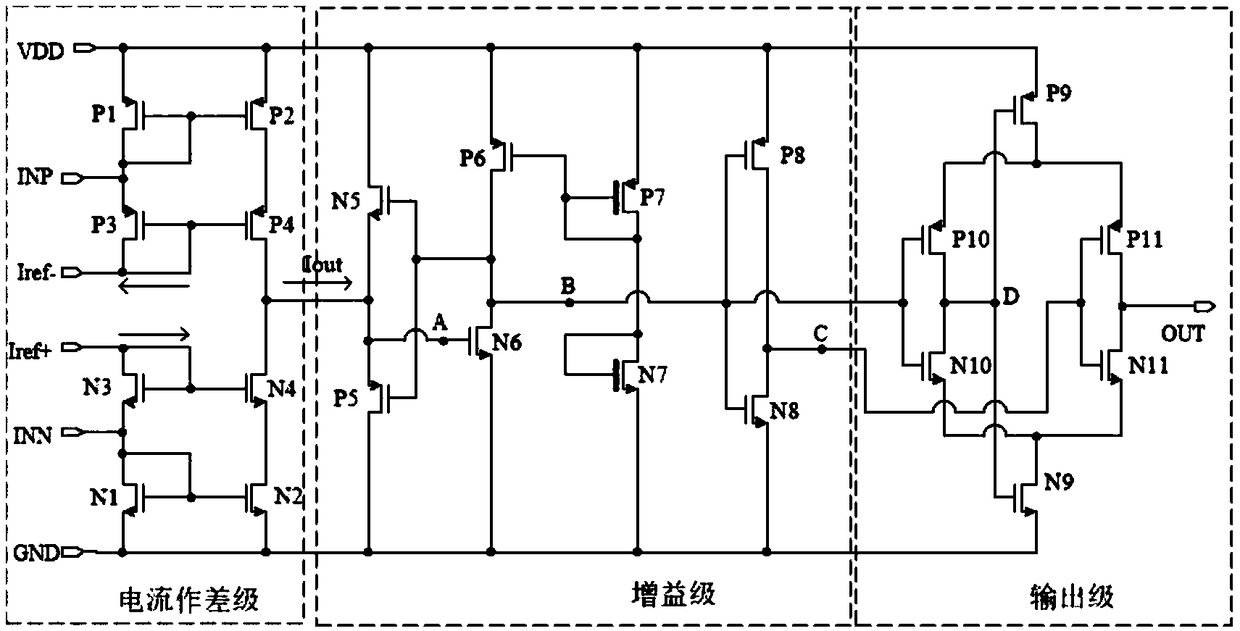
[0025] A current comparator, the specific circuit is as figure 1 As shown, it includes a current differential stage, a gain stage and an output stage; the current comparator body is composed of PMOS transistors P1~P11 and NMOS transistors N1~N11;

[0026] Among them, the current is used as a differential stage, including NMOS transistors N1~N4 and PMOS transistors P1~P4;

[0027] Gain stage, including NMOS transistors N5-N8 and PMOS transistors P5-P8;

[0028] Output stage, including NMOS transistors N9~N11 and PMOS transistors P9~P11;

[0029] The connection relationship of each circuit is as follows:

[0030] The source of the PMOS transistor P1 is connected to the source of the PMOS transistor P2 and connected to the power supply terminal VDD; the gate of the PMOS transistor P1 is connected to the drain, and simultaneously connected to t...


PUM


Abstract

The invention discloses a current comparator, comprising a current difference stage, a gain stage and an output stage, wherein the current difference stage is a cascode current mirror, a current inputend is connected with an MOS transistor with short circuited gate and drain, so that the equivalent input impedance of the current comparator is reduced, and the comparison speed can be improved; thegain stage introduces a common source amplifier of a current source load with feedback, a current source bias voltage is generated by a high threshold voltage tube, so that the bias tube current canbe reduced, and the power consumption is reduced; and the output stage introduces a self-biased differential amplifier, so that the driving capability of the output comparator can be obviously improved. Theoretical analysis and simulation results indicate that the current comparator disclosed by the invention has the characteristics of high precision and high driving capability.

Description

technical field [0001] The invention relates to the field of integrated circuit design, in particular to a high-precision current comparator. Background technique [0002] With the rapid development of integrated circuit technology, SoC has been widely used. Current comparators are found in most SoCs, such as data converter chips, power chips, and even digital isolator chips for industry. The current comparator's speed, accuracy, offset rate and other indicators will affect the performance of the entire system to a certain extent. [0003] In order to achieve greater gain and greater driving capability, traditional current comparators use multi-level gain stages or a multi-level inverter series structure, but multi-level series connection will restrict the accuracy and speed of the comparator. Contents of the invention [0004] In view of this, the technical problem to be solved by the present invention is to overcome the shortcomings of the existing methods and propose ...

Claims


Application Information

Patent Timeline
IPC IPC(8): H03K5/24
CPCH03K5/2481
Inventor 朱智勇
Owner MORNSUN GUANGZHOU SCI & TECH
Why Eureka
Try Eureka