Continuous desalination and dehydration method and device for oily sludge

A technology of oily sludge and sludge, which is applied in sludge treatment through temperature control, dehydration/drying/thickened sludge treatment, petroleum industry, etc., can solve the problem of low efficiency of desalination and dehydration methods, poor desalination effect, and easy desalination and dehydration effect Affected by the nature of raw materials and other issues, it achieves the effects of stable treatment effect, mild operating conditions, simple and economical expansion and transformation

Active Publication Date: 2021-12-17
CHINA PETROLEUM & CHEM CORP +1
View PDF8 Cites 0 Cited by
  • Summary
  • Abstract
  • Description
  • Claims
  • Application Information

AI Technical Summary

Problems solved by technology

[0006] The purpose of the present invention is to provide a method that can continuously treat oily sludge and separate oil from water, aiming at the defects of the existing oily sludge desalination and dehydration methods, such as low efficiency, poor desalination effect, and the desalination and dehydration effect is easily affected by raw material properties. Continuous desalination and dehydration method and device for oily sludge with short time, good desalination and dehydration effect, and stable desalination and dehydration effect

Method used


Image

  • Continuous desalination and dehydration method and device for oily sludge

Examples


Embodiment 1

[0072] This example is used to illustrate the method for desalination and dehydration of oily sludge of the present invention.

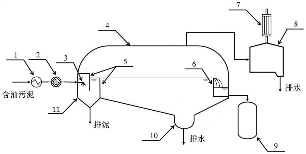
[0073] use figure 1In the device shown, the oil production sludge (water content 30% by weight, salt content 1258mg NaCl / L, mechanical impurity content 27.4% by weight, and the balance is oil content) is continuously transported at a flow rate of 1.5kg / h In the closed system of the pipeline, it is heated by the heater 1 to obtain a pressurized superheated material with a temperature of 160 ° C, and then it is continuously pumped to the dehydration tank 4 by the screw pump 2 with heat preservation and pressure, and the feed distributor 3 at the inlet is sprayed into the steady flow tank 11 provided there, and enter the main body of the dehydration tank 4 in the normal pressure system (about 101.3kPa) through the U-shaped flow channel, so that the superheated material under pressure is instantly vaporized, and the vaporized steam is condensed by the co...

Embodiment 2

[0076] This example is used to illustrate the method for desalination and dehydration of oily sludge of the present invention.

[0077] According to the method described in embodiment 1, the difference is:

[0078] The oily sludge is heated by the heater 1 to obtain a pressurized superheated material with a temperature of 150° C. After vaporization, the condensed water collected in the light component reflux tank 6 accounts for 5% by weight of the water content of the oily sludge;

[0079] The material in the dehydration tank 4 is kept at 80° C. for oil-water separation, and the residence time is 80 minutes.

[0080] Among them, the obtained purified oil had a water content of 2.3% by weight and a dehydration rate of 92.5%; a salt content of 110.7 mgNaCl / L and a desalination rate of 91.2%.

Embodiment 3

[0082] This example is used to illustrate the method for desalination and dehydration of oily sludge of the present invention.

[0083] According to the method described in embodiment 1, the difference is that the oil sludge processed is the mechanical cleaning oil sludge of refinery oil tank, and its water content is 24.9% by weight, and the salt content is 847mg NaCl / L, and mechanical impurity is 45% by weight. The amount is the oil content;

[0084] Among them, the obtained purified oil had a water content of 4.4% by weight and a dehydration rate of 82.3%; a salt content of 91.7 mgNaCl / L and a desalination rate of 89.2%.


PUM

PropertyMeasurementUnit
dehydration rateaaaaaaaaaa
salt rejection rateaaaaaaaaaa
dehydration rateaaaaaaaaaa

Abstract

The invention relates to the field of oil sludge treatment, in particular to a continuous desalination and dehydration method and device for oily sludge. The method for continuous desalination and dehydration of oily sludge comprises: (1) continuously heating the oily sludge under airtight conditions to obtain pressurized superheated material; (2) continuously sending the pressurized superheated material to the In the system, the water below 60% by weight in the oily sludge is vaporized to obtain vaporized steam and residual materials; (3) the residual materials are subjected to oil-water separation to obtain purified oil in the upper layer and saline sewage in the lower layer . The method of the invention can continuously process oily sludge, and has short oil-water separation time, good and stable desalination and dehydration effects.

Description

technical field [0001] The invention relates to the field of oil sludge treatment, in particular to a continuous desalination and dehydration method and device for oily sludge. Background technique [0002] A certain amount of oily sludge with different properties is usually produced in the process of crude oil extraction, gathering and refining. Among them, oily sludge is mainly produced in various links such as drilling operation, oil production process, and gathering and transportation process in the process of oilfield action. As the difficulty of oil recovery increases, the production of associated oily sludge also increases, which has formed a huge impact on enterprises. Environmental pressure and economic pressure; in the crude oil refining process, oily sludge mainly comes from oil tank bottom sludge and air flotation scum. Oily sludge is mainly composed of oil, sediment, organic sludge, surfactants and a large amount of water. It has the characteristics of high col...

Claims


Application Information

Patent Timeline
Patent Type & Authority Patents(China)
IPC IPC(8): C02F11/13C10G1/00
CPCC10G1/00C02F11/12C02F11/18
Inventor 赵锐袁清沈明欢桑军强曹晓磊杨宇宁马欣高峰
Owner CHINA PETROLEUM & CHEM CORP
Why Eureka
Try Eureka