Composite component containing amorphous alloy and preparation method of composite component

A technology of amorphous alloys and composite components, which is applied in the field of composite components containing amorphous alloys and its preparation, can solve the problems of good fluidity, high failure risk, and high requirements of amorphous alloys, and achieve simple and easy preparation methods and reduce The effect of high overall weight and high density

Inactive Publication Date: 2019-03-08
DONGGUAN JIANYE MATERIAL TECH CO LTD
View PDF11 Cites 2 Cited by
  • Summary
  • Abstract
  • Description
  • Claims
  • Application Information

AI Technical Summary

Problems solved by technology

Conventional bonding methods include welding, bonding, etc. However, in the welding process, the secondary heat effect generated is likely to cause the crystallization of the amorphous alloy and the embrittlement of the weld, thereby affecting the bonding performance; in the bonding process, the pretreatment process The requirements for the surface roughness and cleanliness of the materials to be connected are high, and an interface adhesive must be used, which not only increases the complexity of the process, but also the strength and firmness of the bond are limited by the adhesive. The failure speed of the lower adhesive is accelerated, and it is easy to age and break
There is also a method of using a mold to shape the two, but the method of mold processing is selective to the composite material and is not suitable for all materials, and the amorphous alloy has good fluidity, and the overall system has high requirements for temperature control. The composite components made of the advanced mold system not only have weak bonding force at the junction, but also have low density of the amorphous alloy, which affects the dimensional stability of the overall composite component and reduces the strength of the composite component.
In the prior art, there are also amorphous alloy composite component forming methods that use various stages of temperature rise and then compound, but they have not been widely used due to problems such as high processing costs and high failure risks.

Method used


Image

  • Composite component containing amorphous alloy and preparation method of composite component
  • Composite component containing amorphous alloy and preparation method of composite component
  • Composite component containing amorphous alloy and preparation method of composite component

Examples


Embodiment 1

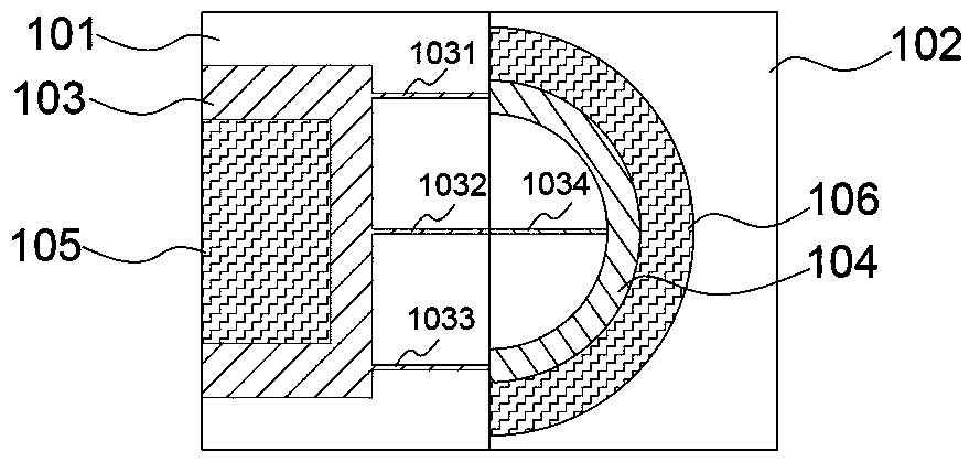
[0033] as attached figure 1 Shown is a schematic diagram of the molding cavity of the composite component in Example 1, so as to further describe the molding method and structure of the composite component in the present invention in detail.

[0034] In this embodiment, a mold is used to extrude the composite member. Specifically, the mold includes a punch 101 and a die 102 with matching shapes. The punch 101 is provided with a melt extrusion cavity 103. The melt extrusion cavity is a feeding cavity for low melting point materials. Similar to a common mold system, the melt extrusion cavity One side of the push rod structure matching the shape of its feed channel is used as a structure for pushing the molten raw material of low melting point material into the molding cavity. Although this structure is not marked in the accompanying drawings of the present invention, it does not Hinder the understanding of the core technical points in the present invention. A molding cavity 10...

Embodiment 2

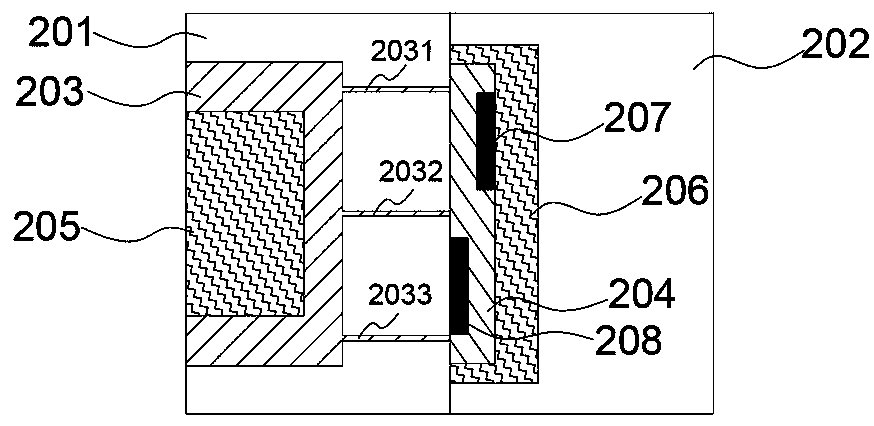
[0042] The schematic diagram of the molding cavity of the composite component in this embodiment is as attached figure 2 As shown, its structure is substantially similar to that in Example 1. Specifically:

[0043] A mold is used to extrude the composite member. The mold includes a punch 201 and a die 202 with matching shapes. The punch 201 is provided with a melting extrusion chamber 203, which is a feeding chamber for low melting point materials, which is different from ordinary The mold system is similar. The push rod structure on one side of the melt-extrusion cavity matched with the shape of the feed channel is used to push the molten raw material of the low-melting point material into the forming cavity. Cavity 204 is the final shaped cavity of the composite component. The extrusion cavity 203 communicates with the molding cavity 204 through runners 2031 , 2032 , 2033 , and the punch 201 is provided with an induction heating device 205 , and the concave die is provide...

Embodiment 3

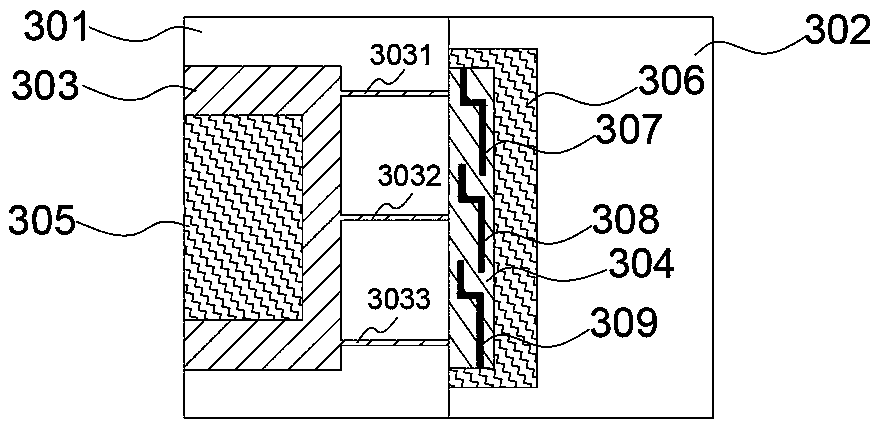
[0048] The schematic diagram of the molding cavity of the composite component in this embodiment is as attached image 3 As shown, its structure is substantially similar to that in Example 1. Specifically:

[0049] A mold is used to extrude the composite member. The mold includes a punch 301 and a die 302 with matching shapes. The punch 301 is provided with a melting extrusion chamber 303, which is a feeding chamber for low melting point materials, which is different from ordinary The mold system is similar. The push rod structure on one side of the melt-extrusion cavity matched with the shape of the feed channel is used to push the molten raw material of the low-melting point material into the forming cavity. Cavity 304 is the final shaped cavity of the composite component. The extrusion chamber 303 communicates with the molding chamber 304 through flow channels 3031 , 3032 , 3033 , and the punch 301 is provided with an induction heating device 305 , and the concave die 302...


PUM

PropertyMeasurementUnit
melting pointaaaaaaaaaa
thicknessaaaaaaaaaa

Abstract

The invention discloses a composite component containing an amorphous alloy. The composite component comprises an amorphous alloy prefabricated assembly and a low melting point assembly. The amorphousalloy prefabricated assembly comprises one or more amorphous alloy prefabricated parts, and the low melting point assembly is a combination part comprising a plurality of low melting point materials;the low melting point materials are polymer materials or metal materials with the melting point being lower than 800 DEG C; and the thickness of each amorphous alloy prefabricated part is 0.1-6 mm. The prefabricated assembly with the specific shape is prefabricated through the characteristics that the amorphous alloy has high strength and can be used for forming a complex structure, then the lowmelting point assembly is injected into a mould to be combined with the prefabricated amorphous alloy to form and prepare the composite component, the composite component simultaneously has the characteristics of high strength of the amorphous alloy and high plasticity of the low melting point assembly, thus the prepared composite component can still have sufficient strength and impact resistanceperformance at the weak position of the significantly-thinned component or the component of a special-shaped structure, and meanwhile, the overall weight of the component can also be decreased.

Description

technical field [0001] The invention belongs to the field of metal composite materials, and in particular relates to a composite member containing an amorphous alloy and a preparation method thereof. Background technique [0002] Structural parts in the existing technology tend to be more and more lightweight. For example, in electronic products, their design is getting smaller and smaller, and their functions are more concentrated. As a structural part, it must meet the functions of connecting, fixing and supporting in the product. , but also meet the index requirements such as strength and impact performance, and at the same time, it must be light and thin and have a good appearance effect. Existing single materials are often difficult to meet all the above requirements. For example, plastic materials, although light and thin, have low strength, appearance and use feel, which are not as good as metal materials. Commonly used metal materials, such as stainless steel, have h...

Claims


Application Information

Patent Timeline
Patent Type & Authority Applications(China)
IPC IPC(8): B22D19/16C22C45/00C22C45/02C22C45/04C22C45/10
CPCB22D19/16C22C45/00C22C45/001C22C45/005C22C45/02C22C45/04C22C45/10
Inventor 黄利敏
Owner DONGGUAN JIANYE MATERIAL TECH CO LTD
Why Eureka
Try Eureka