Mini-LED liquid crystal display backlight structure based on quantum dots and preparation method of mini-LED liquid crystal display backlight structure

A liquid crystal display and backlight structure technology, applied in optics, nonlinear optics, instruments, etc., can solve the problems of uneven brightness and color, fragility of electrodes and wires, large quantity, etc., and achieve simple preparation process, gentle lamination process, Effect of Narrow Emission Spectrum

Inactive Publication Date: 2019-03-15
GUANGDONG POLY OPTOELECTRONICS
View PDF6 Cites 17 Cited by
  • Summary
  • Abstract
  • Description
  • Claims
  • Application Information

AI Technical Summary

Problems solved by technology

It is difficult for the quantum dot fluorescent conversion layer and the micro-LED blue light chip to be perfectly bonded together. For example, the surface of the chip is not resistant to external forces, the size of a single LED chip is small, the number is large, the surface structure of the chip is complex, and the electrodes and wires are fragile. During the process, it is difficult for the adhesive layer to fully contact the chip surface and it is difficult to fully and uniformly bond the quantum dot layer to the backlight chip substrate
After bonding, the surface of the adhesive layer cannot fully contact each chip, resulting in loss of brightness, and the uneven surface will lead to inconsistent light angles, uneven brightness and color, and low bonding strength.

Method used


Image

  • Mini-LED liquid crystal display backlight structure based on quantum dots and preparation method of mini-LED liquid crystal display backlight structure
  • Mini-LED liquid crystal display backlight structure based on quantum dots and preparation method of mini-LED liquid crystal display backlight structure
  • Mini-LED liquid crystal display backlight structure based on quantum dots and preparation method of mini-LED liquid crystal display backlight structure

Examples


Embodiment 1

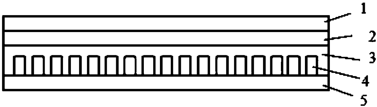
[0045] A quantum dot-based micro-LED liquid crystal display backlight structure, such as figure 2 shown. Prepared by:

[0046] (1) Fix the micro-LED blue-light chip on the substrate by welding to form a small-pitch micro-LED blue-light chip substrate;

[0047] (2) Spread the optical coating composition evenly on the substrate by coating, heat and cure at 110° C. for 10 minutes to form a quantum dot fluorescence conversion layer with a thickness of 100 μm;

[0048] (3) Evenly coat the bonding layer on the quantum dot fluorescence conversion layer, and cure and heat at 110°C for 5 minutes;

[0049] (4) Spread the adhesive evenly on the bonding layer by flow coating, heat and cure at 110°C for 10 minutes to form an adhesive layer, the thickness of which is higher than the height of the micro LED blue light chip;

[0050] (5) Bonding the adhesive layer to the micro-LED blue light chip substrate to form a micro-LED liquid crystal display backlight structure based on quantum dot...

Embodiment 2

[0053] A quantum dot-based micro-LED liquid crystal display backlight structure, such as Figure 4 As shown, the bottom of the micro-LED blue light chip substrate is a flat plate, and the surroundings extend upward to form a hollow structure, which has high reflectivity to the visible light band and is resistant to blue light radiation. Prepared by:

[0054] (1) Fix the micro-LED blue-light chip on the substrate by silica gel bonding to form the micro-LED blue-light chip substrate;

[0055] (2) Spread the optical coating composition evenly on the substrate by coating, and heat and cure at 110°C for 15 minutes to form a quantum dot fluorescence conversion layer with a thickness of 100 μm;

[0056] (3) Apply the bonding layer evenly on the quantum dot fluorescence conversion layer, and heat and cure at 110° C. for 5 minutes;

[0057] (4) Spread the adhesive evenly on the micro LED blue light chip substrate by flow coating, heat and cure at 50°C for 30 minutes to form an adhesi...

Embodiment 3

[0060] A quantum dot-based micro-LED liquid crystal display backlight structure, such as Figure 5 shown. The bottom of the micro-LED blue light chip substrate contains protrusion fillers, which are densely arranged in a grid form to form a large number of small cavity structures, and the micro LED blue light chips are fixed in the small cavities. The small cavity can further reflect blue light, enhance luminous efficiency, form a protective effect on the micro-LED chip, and at the same time have the function of high temperature resistance and prevent chip displacement. The material of the substrate is specially treated EMC or PC material. Prepared by:

[0061] (1) Fix the micro-LED blue-light chip on the substrate by silica gel bonding to form the micro-LED blue-light chip substrate;

[0062] (2) Spread the optical coating composition evenly on the substrate by coating, and heat and cure at 110°C for 15 minutes to form a quantum dot fluorescence conversion layer with a thi...


PUM

PropertyMeasurementUnit
sizeaaaaaaaaaa
thicknessaaaaaaaaaa
thicknessaaaaaaaaaa

Abstract

The invention relates to a mini-LED liquid crystal display backlight structure based on quantum dots and a preparation method of the mini-LED liquid crystal display backlight structure. The mini-LED liquid crystal display backlight structure comprises a mini-LED blue light chip substrate, an adhesive layer, a laminating layer and a quantum dot fluorescent conversion layer in sequence form bottom to top. The mini-LED liquid crystal display backlight structure based on the quantum dots has the advantages that the quantum dots have very narrow emission spectra, ultra-wide color gamut of liquid crystal display can be achieved, a required laminating process is mild, the quantum dot fluorescent conversion layer can be fully, tightly and flatly combined with a mini-LED blue light chip, a luminousstructure of the mini-LED blue light chip cannot be destroyed, the backlight structure can be formed through one-time assembly, and the mini-LED liquid crystal display backlight structure is suitablefor producing backlight sources of liquid crystal displays in large area.

Description

technical field [0001] The invention relates to a micro-LED liquid crystal display backlight structure based on quantum dots and a preparation method thereof. Background technique [0002] At present, there are two main ways to realize the white backlight in liquid crystal display (LCD): one is to use blue LED to excite the phosphor to emit yellow light, and the blue light and yellow light are mixed to produce white light; the other is to use red, green and blue three LEDs with different colors can mix red, green and blue light to produce white light. However, the above two methods have disadvantages. The first method has a narrow color gamut of the display due to the wide emission spectrum of the phosphor, while the second method can achieve a wider color gamut, but the cost is higher. . [0003] Micro LED technology, also known as "submillimeter light-emitting diodes", are tiny LEDs with a chip size of about 100 microns. Hundreds of tiny LED chips are arranged in a matr...

Claims


Application Information

Patent Timeline
Patent Type & Authority Applications(China)
IPC IPC(8): G02F1/13357H01L25/075H01L33/48H01L33/50H01L33/52
CPCG02F1/133603G02F1/133614H01L25/0753H01L33/486H01L33/507H01L33/52H01L2933/0033H01L2933/0041H01L2933/005
Inventor 蔡梁强涂奎元崔正星余锡钊李阳
Owner GUANGDONG POLY OPTOELECTRONICS
Why Eureka
Try Eureka